CABRIOLE’
CRAMARO TS S.r.l. – 37044 COLOGNA V.TA (VR) - VIA QUARI DESTRA, 71/G TEL. +39 0442/411688 / FAX + 39 0442/411690
E-MAIL info@cramaro.com WEBSITE: http://www.cramaro.com - Manual n° MCA016-EN-ED00 – date 15/01/15
page 30
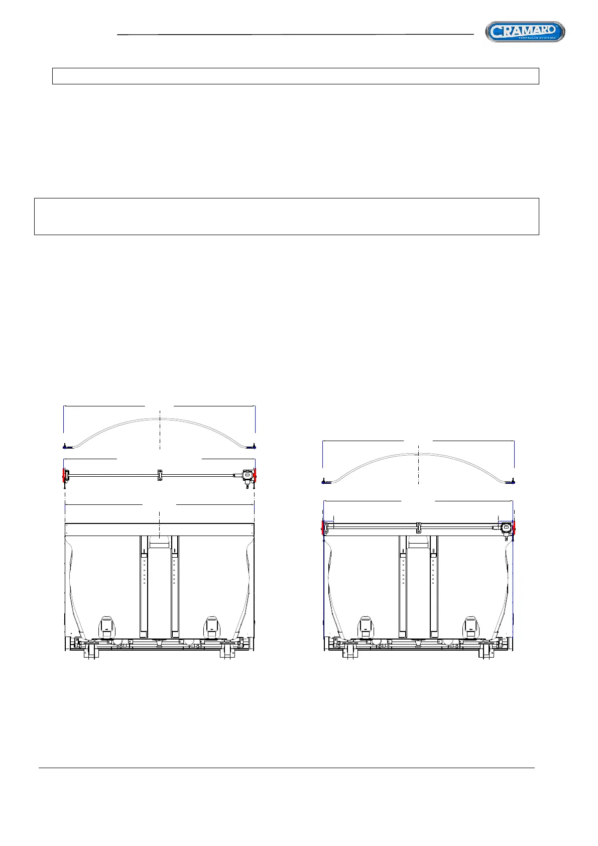
FIG 42
20
20
LA = LP
LP = LC + 12+12 mm
>> LC <<
LA = LP
>> LC <<
ASSEMBLING THE MECHANICAL PART
- FRONT MOVEMENT UNIT -
As we have seen, the FRONT PULLING UNIT must be applied to the front of the container, precisely on the
front façade of the cab-shield.
The activation system can be MANUAL, ELECTRIC or HYDRAULIC and the assembly of these three versions
is exactly the same
The pulling mechanism is normally assembled on the LEFT of the cab-shield
(DRIVER SIDE) so that, especially in the MANUAL version, the Drive crank is near the driver door for easy
use as soon as he descends from the vehicle
1. After having carefully checked the width of the bows supplied in the tarpaulin assembly kit (THE
MEASUREMENT TO CONSIDER IS THAT CONCERNING THE CENTRE OF THE PINS WHERE THE BOW
SLIDING ROPES ARE INSERTED), position the pulling front unit on the front façade of the container and, making
sure that the upper edge of the front pulleys is higher than the side edge of the container by about 20mm and
that the side pulleys protrude from the side edges of the container both on the right and left side by the same
measurement as the bow plus (about 12mm) - FIG. 43
N.B. THE FIGURES SHOW SYSTEM ASSEMBLY IN ITS MANUAL CONFIGURATION, BUT THE
ASSEMBLY OF THE OTHER SYSTEMS IS EXACTLY THE SAME
2. Before securing them, make sure that all the shaft supports are aligned with one another, as any misalignments
make movement difficult and can cause irreparable damage to the tarpaulin pulling mechanism.