The MMU and each ESU have two power cooling modules (PCMs), and each SSU has four power
cooling modules (PCMs) with power switches, located next to the MMU I/O modules.
d. Verify that the rack PDU circuit breakers are tripped (in the OFF position).
To turn circuit breakers off, insert a small flat-blade screwdriver into the slot on the OFF button on the
circuit breaker.
e. Verify that no power is enabled to the MGMT switches.
Either remove the power cord from the power source or switch off the PDU.
2. Enable power to the rack using one of the following methods:
a. For rack PDUs that have power switches:
● Verify that the power cords for the management switches are inserted into the PDUs.
● Place each PDU power switch, if any, in the ON position. (PDUs from some manufacturers have
multiple lines, with one power switch for each line; some have none. Verify that each line is powered
on.)
b. For rack PDUs without power switches, plug the PDU cords into the facility power receptacles.
3. Enable power to the 5U84 ESUs, if any.
a. Place the power switches in the ON position.
The power switches for an ESU are on the PSU.
b. Wait 30 seconds for the drives to spin up.
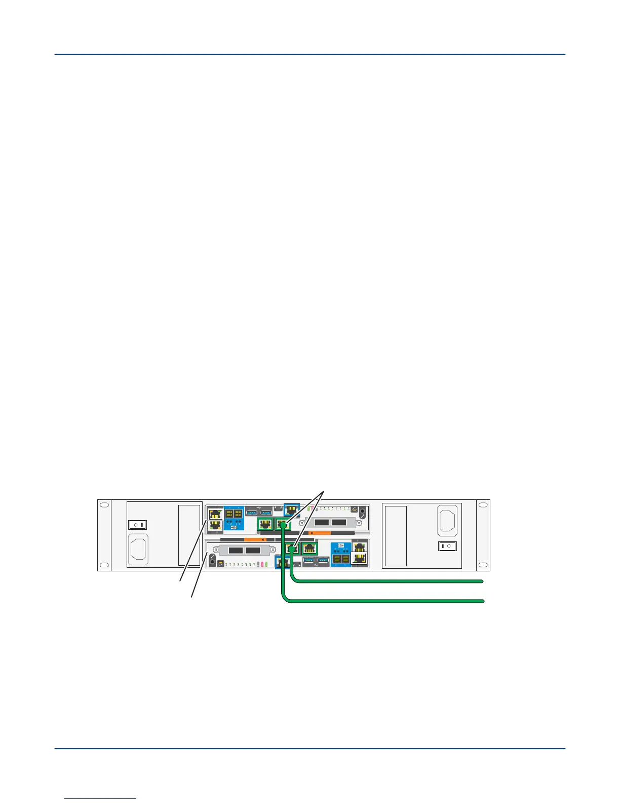
4. Cable the primary and secondary MGMT nodes to the public network (pub0), as shown.
NOTE: Verify that the primary and secondary MGMT nodes (EAC logical nodes n000 and n001) are
connected to the external administration network (EAN) through the pub0 interface.
Figure 47. Cable SMU to External Administration Network
A
B
To external
administration
network (EAN)
EAC A Node n000
EAC B Node n001
pub0 interfaces (NIC 5)
SMU
5. Connect a console, or PC to the primary MGMT controller using a Micro HDMI cable P/N 101811700 or an
RS-232 serial cable to monitor the boot messages.
Power On the ClusterStor L300 and L300N System
57