Chapter 2 Installation
33
Chapter 2 Installation
aged
g
r
o
kets
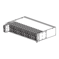
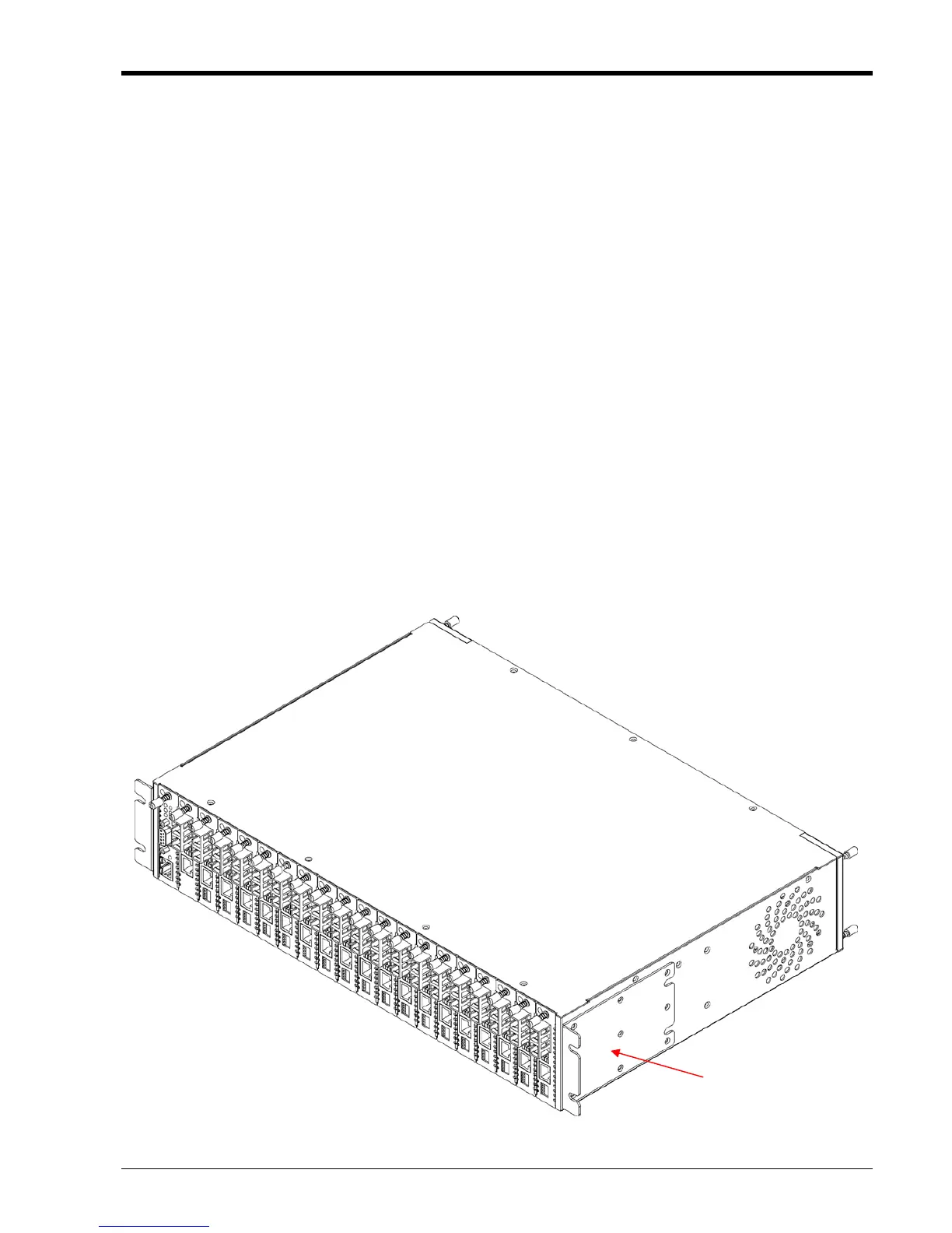
2.3.1 Rack mounting
Figure 2-1 Standard 19" Rack-Mount Installation of FRM220 Unit requires 2RU space
Bracket may install for
19" or 23" mounting.
(factory installed)
2.1 Introduction
The Installation chapter will cover the physical installation of the FRM220, Rack Mount In-Band Man
Series Fiber Converter Platform Chassis, the electrical connections, interface connections and cablin
requirements. A brief overview of the functional components such as main unit and management options will also
be outlined in this chapter.
Required Tools
You will need these tools to install the FRM220:
Number 2 Phillips screwdriver for the 3mm and the 12-24 rack installation screws.
Wrist strap or other personal grounding device to prevent ESD occurrences.
Antistatic mat or antistatic foam to set the equipment on.
2.2 Site Preparation
Install the FRM220 within reach of an easily accessible grounded AC outlet or three wire (-48VDC, Powe
return, Earth Ground) central office power. The AC outlet should be capable of furnishing 100 to 240 VAC. Refer t
2.4 Electrical Installation. Allow at least 10cm (4 inch) clearance at the front of the FRM220 for the Fiber and other
copper cables.
2.3 Mechanical Assembly
The FRM220 is designed for rack mount installation and will require 2U space in a standard EIA 19" or 23" rack.
The FRM220 has two removable fan units that install in the rear side of the chassis. Without fans, excessive
temperatures within the unit might cause it to electrically shutdown. The FRM220 chassis is delivered completely
assembled, however power modules and converter cards may or may not be installed in the chassis upon delivery.
The rack mount adapters may be placed along the front or centrally located on the chassis. The same brac
also allow installation into a 23" rack and in this configuration, central mounting is recommended.

 Loading...