Chapter 2 Installation
35
2.4 Electrical Installation
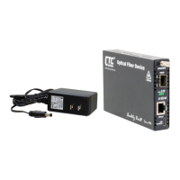
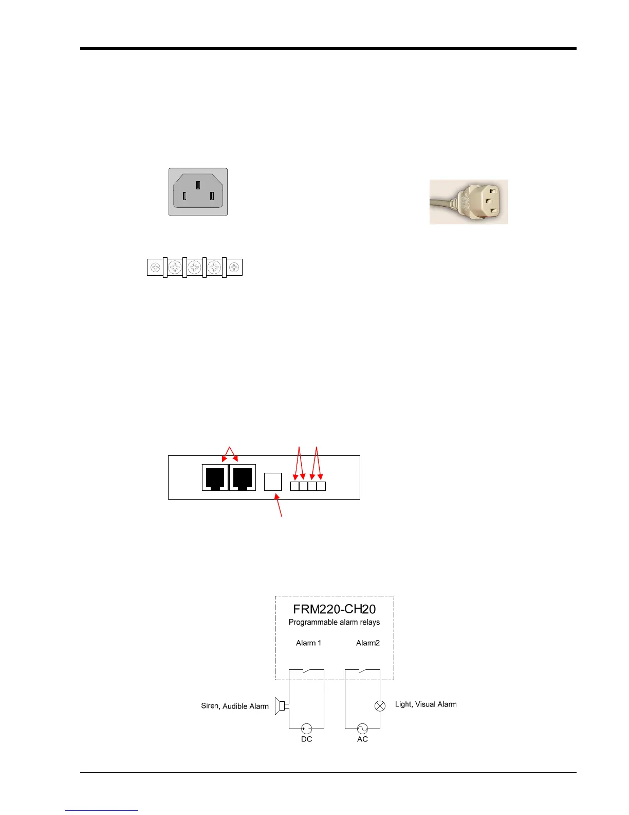
With an AC power module, AC power is supplied to the FRM220 through a standard IEC C14 3-prong
receptacle, located on the rear of the module. Any national power cord with IEC C13 line plug may be used to
connect AC power to the power module. With a DC module, DC -48V is connected to the terminal block located on
the rear of the module, observing the proper polarity. The FRM220 should always be grounded through the
protective earth lead of the power cable in AC installations, or via the frame ground connection for DC installations.
Figure 2-4 IEC (AC) & terminal block (DC) power connector pin assignment
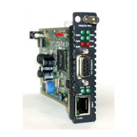
2.5 Alarm Installation
The alarm relay provides one set of Power Failure contacts (normally open) and another set of FAN Failure
contacts (normally open) contacts for monitoring the power and fans condition of the FRM220. The alarm contacts
may also be programmed through the management interface to react to different fault conditions.
Figure 2-6 Example of electrical circuit for visual and audible alarms
Left: Live line
Right: Neutral line
Middle: Ground
Left: -V (-48V)
Right: +V (0V)
Middle: Frame Grou
DC IN
-V FG +V
36~60VDC
nd
IEC C13 line plug
125VAC 1A
110VDC 0.6A
30VDC 4A
IN OUT
Alarm Contacts
1 2
Chassis ID
Cascade Ports
Figure 2-5 Alarm Relay Contacts and Cascade Ports
 Loading...