HYDRO. DRIVE AND BRAKE SYSTEM
47
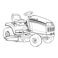
10c. Carefully lower the PTO clutch and any
associated hardware. See Figure 5.56.
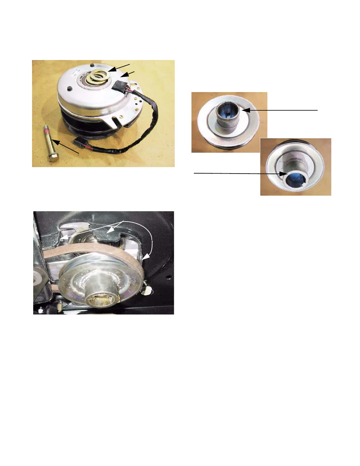
10d. Slide the pulley off of the engine crankshaft.
The belt will clear the belt keepers as the
pulley comes down. See Figure 5.57.
10e. Remove the belt.
Figure 5.56
Washers (2)
PTO clutch
Crankshaft bolt
Figure 5.57
Belt keepers
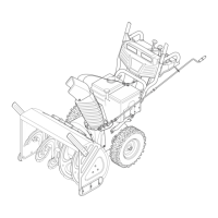
NOTE: The flat edge of the crankshaft pulley
faces the electric PTO clutch. The end with the
inside diameter chamfered goes against the fillet
near the base of the crankshaft.
See Figure 5.58.
11. If the drive belt failed prematurely, identify and
correct the cause of the failure before installing a
new belt.
12. Install the new belt by reversing the steps used
to remove it.
Belt installation notes:
• Install only a correct OEM belt. Incorrect belts
may cause problems that effect the performance
and/or safety of the tractor.
• Apply a small amount of anti-seize compound to
the engine crankshaft before installing the crank-
shaft pulley.
• Apply a small amount of thread locking com-
pound such as Loctite 271
TM
(red) to the threads
of the crankshaft bolt.
• Tighten the bolt to a torque of 36-50 ft--lbs.
(50-68 N-m).
Figure 5.58
Top of
crankshaft pulley
Bottom of
crankshaft pulley
 Loading...