11 88
ETHERNET INTERFACE
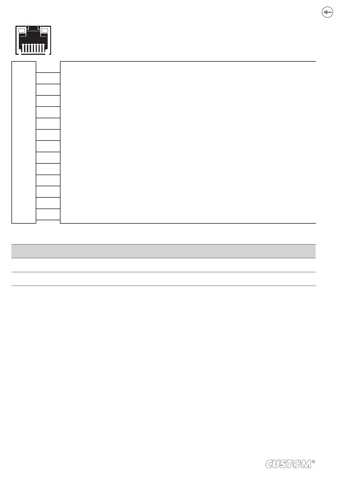
Female RJ45 connector
J5
1 TPOUT +
2 TPOUT -
3 TPIN +
4 GND
5 GND
6 TPIN -
7 n.c
8 n.c
9 +3.3 V
10 LED-LAN
11 +3.3 V
12 LED-LNK
13 Shield
14 Shield
LED FUNCTION
LED-LNK Link (yellow color): the LED lights up when a connection is active.
LED-LAN Rx/Tx: (green color): the LED lights up when occurs a data reception or transmission.
To directly connect the device to a Personal Computer, use a Cross-Over Ethernet cable.
To connect the device to a hub device, use an UTP Ethernet cable (Pin to Pin).
The pinout shown in table represents the input signals to component J5 before the isolation voltage transformer (through-
hole pin).
30