6D-Link DCS-5300 User Manual
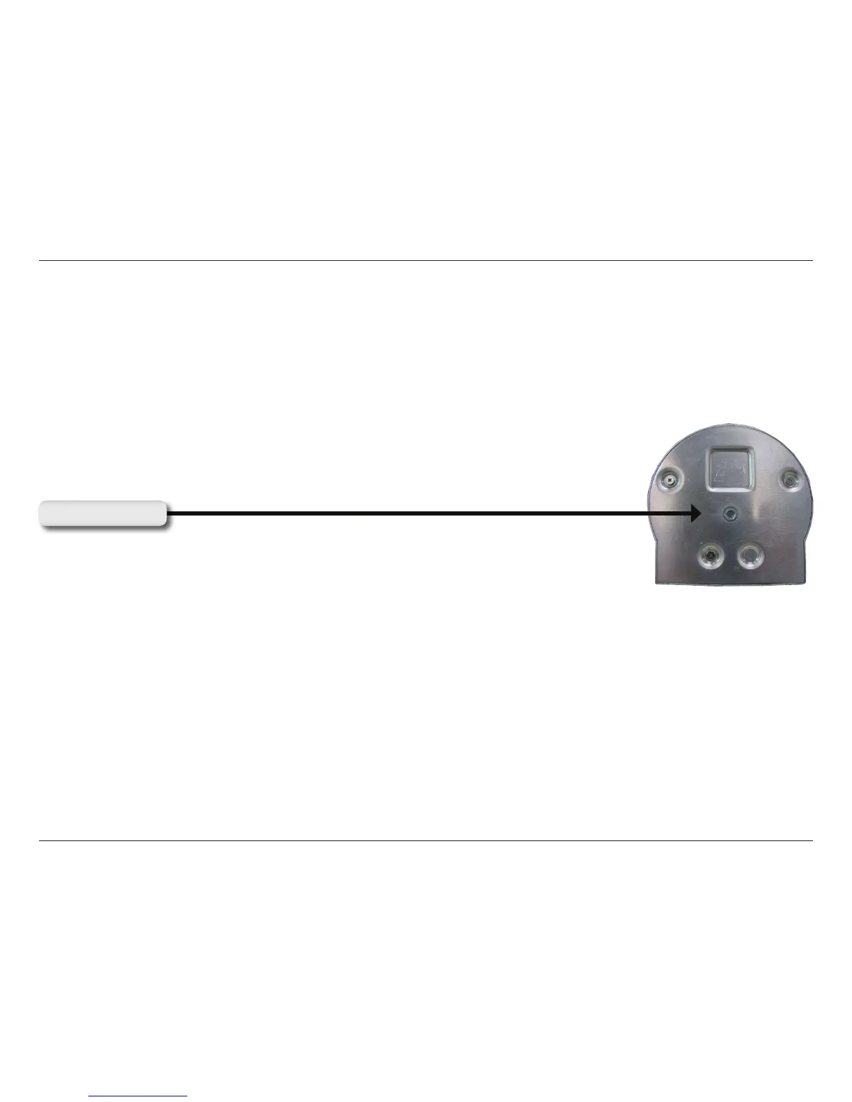
Note: Located on the bottom panel of the DCS-5300, the socket is used to connect the
camera stand to the Network Camera by attaching the screw head on the camera stand to
the Network Camera.
The Power LED (Light-Emitting Diode) is positioned on the right side of the Network Camera lens. As soon as the power
adapter is connected to the Network Camera, the power LED will ash red and green several times. The DCS-5300 is
conducting a self-test. Upon passing the self-test, the LED will turn green to indicate a good connection to an Ethernet
port or red to indicate no connection has been made.
I/O Connector - The DCS-5300 provides a terminal block with two pairs of connectors situated on the back panel.
One pair is for input and the other is for output. The I/O connectors provide the physical interface to send and receive
digital signals to a variety of external alarm devices. Please refer to the appendix in this manual for detailed
information.
Bottom Panel
Socket for stand
Power LED