ENGLISH
50
12. DESCRIPTION OF CONTROL PANEL
The electronic control integrated in the system is of the type with inverter and it makes use of flow, pressure and temperature sensors, also
integrated in the system. By means of these sensors the system switches on and off automatically according to the utility’s needs and it is
able to detect conditions of malfunction, to prevent and indicate them. The Inverter control ensures different functions, the most important
of which, for pumping systems, are the maintaining of a constant pressure value in delivery and energy saving. The inverter is able to:
• keep the pressure of a hydraulic circuit constant by varying the rotation speed of the electropump. In operation without an inverter
the electropump is unable to modulate and, when there is an increase of the request for flow, the pressure necessarily decreases,
or vice versa; this means the pressures are too high at low flow rates or too low when there is an increased request for flow.
• By varying the rotation speed according to the instantaneous request of the utility, the inverter limits the power supplied to the
electropump to the minimum necessary to ensure that the request is satisfied. Instead, operation without an inverter contemplates
operation of the electropump always and only at maximum power.
The system is configured by the manufacturer to satisfy the majority of installation cases, that is:
• Type of product: booster;
• Operation: constant pressure;
• Set-Point [SP]: desired value of constant pressure. Value configured by the manufacturer SP = 3.0 bar;
• Restart Pressure: Reduction of pressure to restart. Value configured by the manufacturer RP = 0.3 bar;
• Anti-cycling function: Value configured by the manufacturer Disable
For the definition of the parameters SP and RP, the pressure at which the system starts has the value:
P
_START
= SP – RP = 3.0 - 0.3 = 2.7 Bar
The system does not work if the utility is at a height higher than the equivalent in metres of water column of the Pstart (consider 1 bar =
10 m water column): for the default configuration, if the utility is at a height of at least 27m the system does not start.
12.1. Control panel orientation
The control panel is designed to be placed in the most readable direction for the user: the square shape allows it to be rotated 90° by
90° (Fig. 7).
• Unscrew the 4 screws at the corners of the panel with the accessory tool (if supplied) or a normal torx wrench.
• Do not remove the screws completely, it is recommended to unscrew them only from the thread on the body of the product.
• Be careful not to drop the screws into the system.
• Move the panel, taking care not to stretch the signal cable.
• Replace the panel in its seat with the chosen orientation, taking care not to pinch the cable.
• Tighten the 4 screws with the accessory tool (if supplied) or a normal torx wrench.
12.2. Filling system operation
The priming of a pump is the phase during which the machine attempts to fill the body and the
suction pipe with water. If the operation is successful the machine can work regularly
.
Once the pump has been filled and
the device has been configured, it is possible to connect the
electric power supply after having opened at least one utility on delivery for the first 15 seconds
. If a
flow of water is detected in delivery, the pump is primed and starts its regular work. This is the typical
case of installation below head
. The utility opened in delivery from which the pumped water is
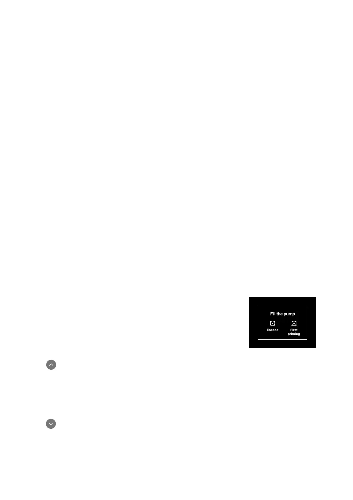
coming out can be closed. If a regular flow in delivery is not detected after 10 seconds, the system
asks for confirmation to enter the primin
g procedure (typical case of installation above head).
Fig. 17: Priming popup
When is pressed the pump enters the priming procedure: it starts working for a maximum time of 5 minutes during which the safety
block for dry operation is not tripped. The priming time depends on various parameters, the most influential of which are the depth of
the water level from which it is drawing, the diameter of the suction pipe, the water-tightness of the suction pipe. On condition that a
suction pipe is used that is no smaller than 1” and that it is well sealed (with no holes or joins from which it can take in air). As soon as
the product detects a regular flow in delivery, it leaves the priming procedure and starts its regular work. The utility opened in delivery
from which the pumped water is coming out can be closed. If after 5 minutes of the procedure the product is still not primed, the interface
display sends a failure message. Disconnect the power supply, load the product adding new water, wait 20 minutes and repeat the
procedure from the moment you put the plug in the socket.
Press confirm that you do not want to start the priming procedure. The product remains in alarm status.