ENGLISH
55
Disabled
Motor manually disabled
Error
Blocking error: the type of error is shown and described in the bottom left corner of the screen
KIWA Sensor Error
“Low suction pressure” error signal
Table 7: System Status Icons
Main Page: Auxiliary Functions Icons
Power Shower
Float
Sleep Mode
Table 8: Auxiliary Functions Icons
Footer: Indications on the status bar
Motor status manually disabled
Presence of an error preventing operation of the electropump
Indicates an Alarm that does not prevent operation of the electric pump
Table 9: Indications on the status bar
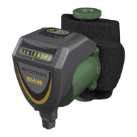
The other menu pages vary with the associated functions and are described later by type of
indication or setting. Once you have entered any menu, the bottom of the page always shows a
summary of the main operating parameters (running status or any fault, current speed and
pressure). This allows a constant view of the machine’s fundamental parameters.
Pages showing parameters can display: numerical values and units of measure of the current
item, values of other parameters linked to the setting of the current item, graphic bar, lists; see
Fig. 21.
Fig. 21: Display of a menu
parameter
13.1.5. Blocking parameter setting by Password
The device has a password-enabled protection system. If a password is set, the parameters of the device will be accessible and visible
but it will not be possible to change them. The password management system is in the “technical assistance” menu and is managed by
means of the parameter PW.
13.1.6. Enabling and disabling the motor
In normal operating conditions, pressing and then releasing both the and keys causes the blocking/release of the motor (self-
holding even after switching off). If there is a fault alarm, the operation described above resets the alarm. When the motor is disabled
this status is shown by the blinking white LED. This command can be activated from any menu page except RF and PW.
13.2. Meaning of the individual parameters
The inverter makes the system work at constant pressure. This regulation is appreciated if the hydraulic plant downstream from
the system is suitably sized. Plants made with pipes with too small a section introduce load losses that the equipment cannot
compensate; the result is that the pressure is constant on the sensors but not on the utility.
Plants that are excessively deformable can create the onset of oscillations; if this occurs, the problem can be solved by adjusting
the control parameters “GP” and “GI” (see paragraph
GP: Proportional gain coefficient and GI: Integral gain coefficient)