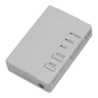
Electric Wiring Work and Initial Setting
Electric wiring work
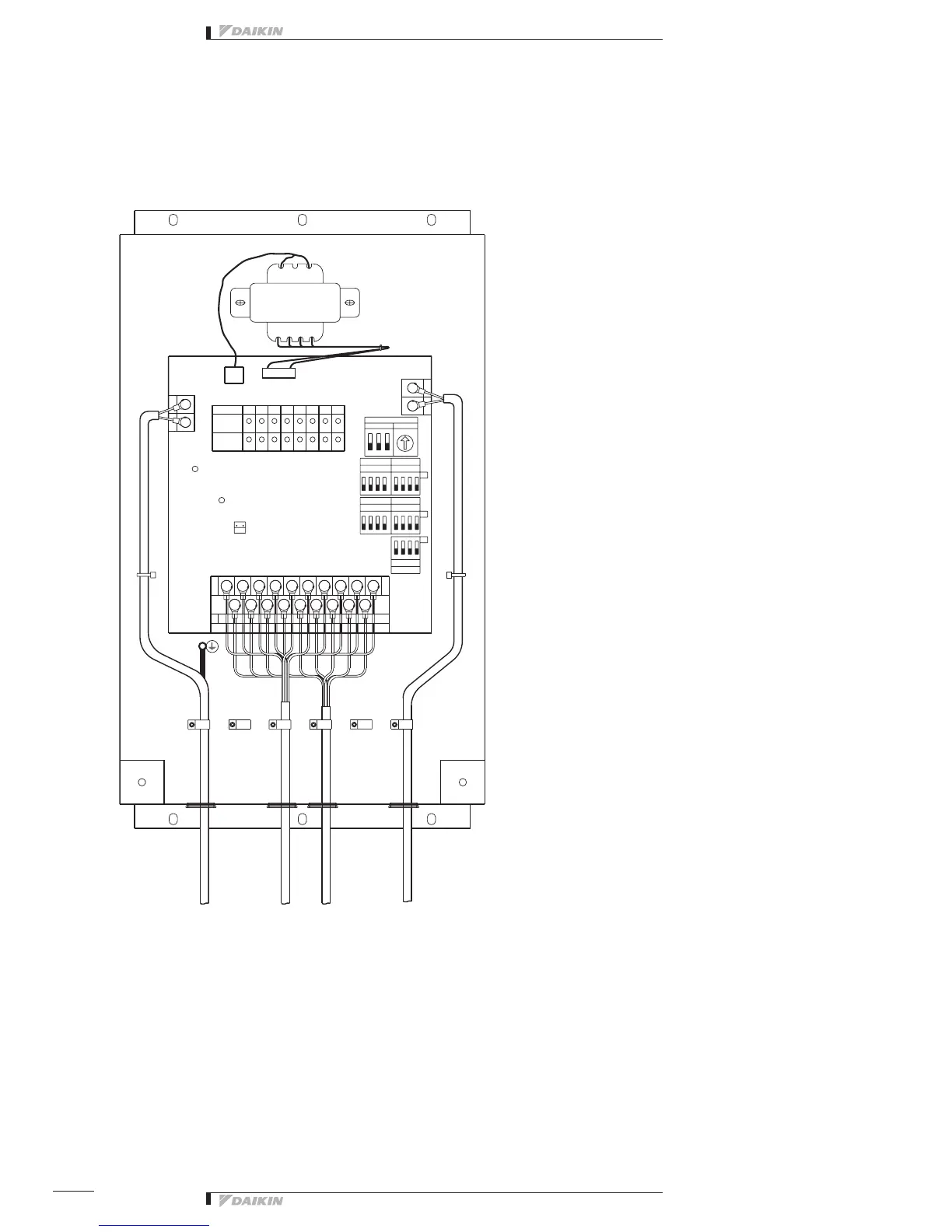
Wiring Lead-In
Forwiringconnection,removethefrontpanel(securedwith2screws)ofthisequipment.
Uponcompletionofoperationgiveninthisparagraphand“2. Initial Setting” below,closethefrontpanelwiththescrews
described above.
×
×
4
ON
DS6
231
RS1 Low
Group No. Set
0
DS1 High
2413
DS3
5
DS2
8
ON
67
7
ON
2
DS5
3
DS4
46581
M6M3 M4
CA
CM M5
A6
M2 M7 M8
A7A4A3 A8
M1
A5A2A1
TP1
2
H9P
H8P
H1P
H10P
H15P
4
H6P
H14P
H7P
H12P
H2P
H16P
H11P
INPUT
H5P
67
H3P
H13P
3185
X2A
F2
F1
N
L
X3M
RED
H17P
X1M
YE
RED
AC200V
~240V
GRN
HAP
X2M
X1A
H4P
×
×
×
×××××××××
×
××××××××
4321
(1)Wireconnectionsandwireclampingshouldbeasshowninthefigureabove
(2)Nosimultaneousclampingisallowedforhigh-voltagewiring(powersupplywiring(L/N)&earthwiring),low-voltage
wiring <Communication wiring (F1/F2), operation input wiring (CM, M1 to 8) and abnormal input wiring (CA, A1 to 8)>
sincemalfunctioningmayresult.Also,incasewherethewiringsdescribedaboveareroutedinparallel,besureto
connectthewiringsatleast50mmapartfromtheother.
ClampClamp
➀
To 1 ~ 200 - 240 V and earth
➁ Tofacilityequipment
➂ Tofacilityequipment
➃ ToterminalsF1,F2ofthe
centralized control equipment or
terminalsF1,F2ofother
equipment (outdoor unit,
DEC101A51, 102A51)
 Loading...