Initial setting
• DEC101A51 Switch Settings
Name Operation OFF ON
DS2
Abnormal input detection Open/Close
(Concentrated address +4 to 7)
Abnormal input detection method
Open: Close (Normal) Æ Open (Abnormal)
Close: Open (Normal) Æ Close (Abnormal)
Open Close
DS3
Abnormal input detection Open/Close
(Concentrated address +0 to 3)
Open Close
DS4
Buzzer output ON/OFF (Concentrated
address +4 to 7)
ON/OFF switching of buzzer output of buzzer unit
upon detection of failure.
ON OFF
DS5
Buzzer output ON/OFF (Concentrated
address +0 to 3)
ON OFF
DS6-1 Startup failure Masking time after detecting operation input. 10 seconds 30 seconds
DS6-2 Failure detection Recovery method upon detection of failure.
Automatic
reset
Retained
DS6-3 Monitor input Detection of failure under halting status. Yes No
Note:
All are set to “OFF” upon shipment from factory.
07
D5
04 13
34 7
09 1108 10
29CA0
05
E6
06 1201
B8
03 1400 1502
F1
2-00 ~ 2-151-00 ~ 1-15
RS2DS1
8
3-00 ~ 3-15
4-00 ~ 4-15
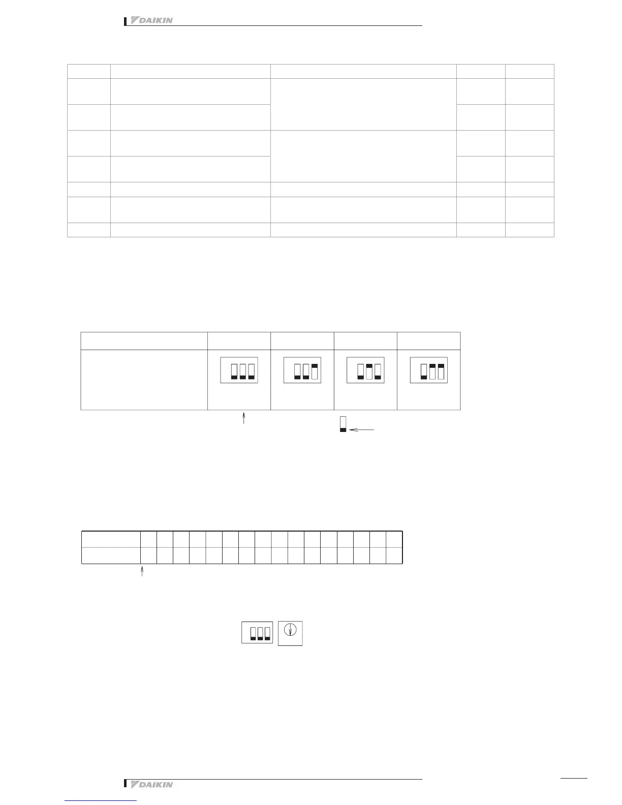
➀ SetthetopaddressofthisequipmentwiththeDIII-NETsettingswitch(DS1/RS1).
UsingtheDIII-NETsettingswitch(DS1),settherangeofAddressNo.thatissetin
thisequipment.AddressNos.1-00to1-15arefactorycontrolledbeforeshipment.
Control range DS1
When a product is discharged
fromthefactory.
<when a product is
dischargedfromthefactory>
Address No. indicates the
followingportioninthiscase
Inthiscase,itfollowsthatthis
equipment uses Address Nos.
1-08 to 1-15.
(8 numbers max.)
1-08
<Example>
When Address No. is
set to 1-08
This indicates the switch knob.
RS1 Switch Setting Table
Position
Address No.
Set Address No. (low order) with the centralized address setting switch (RS1)
Referringtothetablebelow,settheaddressnumberloworder.
(Address Nos. are 1-00, 1-01, --- 1-15, 2-00, --- 4-15.)
Control range DS1 (high order)
setting
(Address range)
ON ON ON ON
High
order
High
order: 1
Low
order
Low order
Low
order: 8
ON
 Loading...