*Numberofcentralizedaddressesused
Thenumberofcentralizedaddressesusedisdeterminedbythetopaddresssetinthisitemandthenumberoffacility
equipment connected that is set in “➂ TP1 Setting (Facility equipment quantity change)”.
Example 1:
Whenthetopaddresswassetto“1-00”andthenumberoffacilityequipmentwassetto“2”,itfollowsthat“1-00”and
“1-01” are being used.
Example 2:
Whenthetopaddresswassetto“3-15”andthenumberoffacilityequipmentwassetto“8”,itfollowsthat“3-15”,“4-00”,
“4-02”, “4-03”, “4-04”, “4-05” and “4-06” are being used.
<CAUTION>
This equipment can use the addresses between “1-00” and “4-15”.
(It is impossible to use Address 5-00 and subsequent addresses, and use any address in duplication.
Example:
Whenthetopaddresswassetto“4-14”,thenumberoffacilityequipmentcannotbesetto“8”.
In this case, set it to “1” or “2”.)
➁DS2&DS3Setting
This switch selects whether the input is abnormal with the abnormal input contact (A1 to A8) open or closed.
OFF(factorypresetbeforeshipment)--------Abnormalintheopencondition
ON - - - - - - - - - - - - - - - - - - - - - - - - - - - - - - - - Abnormal in the closed condition
The relationship between each switch and abnormal input is as described below.
Input A1 : DS2, 3-1
Input A2 : DS2, 3-2
Input A3 : DS2, 3-3
Input A4 : DS2, 3-4
Input A5 : DS2, 3-5
Input A6 : DS2, 3-6
Input A7 : DS2, 3-7
Input A8 : DS2, 3-8
➂ TP1 Setting (Facility equipment quantity change)
Thisfunctionisusedtosetthenumberoffacilityequipmentcontrollablewiththisequipment.
(Thenumberofcontrollablefacilityequipmentfactoryshipmentis8.)
(Setting Method)
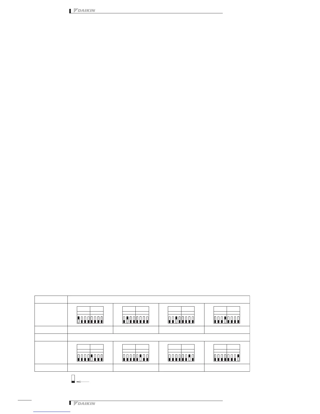
1.Turnthepower“ON”withTP1short-circuitedandchangethequantityoffacilityequipmentaccordingtotheDS4,5
setting.TherelationbetweenDS4,5settingandfaciltyequipmentquantityisasperthetablebelow.
2. Turn the power OFF.
3. Open the TP1 and turn all DS4, 5 switches “OFF”.
4. Turn the power ON again.
5.Short-circuittheTP1,andchecktoseeifthesettingcoincideswiththenumberoffacilityequipmentconnectedtothis
equipment.
6. Finally, open the TP1.
5
DS6
1
DS5
3
DS5
1
8
DS6
DS4
DS5
6
176
1
4
DS6
6
28
57
2
TP1
62
7
1 4
DS6
DS5
35
DS6
4
6
DS5
4
1
82
5
4
DS6
4
6
2 8
1 885
745
2
6
DS5
2
53
 Loading...