By short-circuiting the quantity change TP1 in the normal operating condition, the setting status
canbeconfirmed.
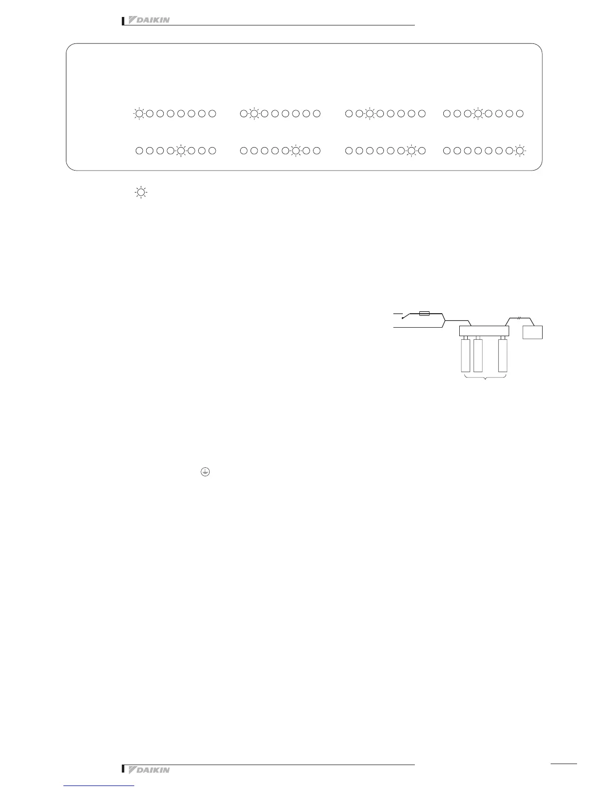
Operation
monitor
This indicates LED lighting.
1 unit 2 units 3 units 4 units
5 units 6 units 7 units 8 units
DEC101A51
...
Centralized
control
equipment
Switch Fuse (10A)
Facility equipment
(8 numbers max.)
Power Supply
(1 ~ 200-240V)
Electric wiring connection
Wiring Procedure
➀ <F1/F2> wiring between this equipment and centralized control equipment is
required.
➁ Theconnectiontothefacilityequipmentandsettingofvariousswitchesare
required.
See the "Wiring with Facility Equipment" paragraph.
➂ Connect the power supply and earth.
See the “Power Supply & Earth Wiring” paragraph.
➃ Forthewiringconnectionandclampingmethod,refertothe“WiringLead-in”
paragraph.
Wiring with Facility Equipment <CAUTION>Thelengthofwiringbetweenthis
equipmentandfacilityequipmentis
100m max.
Power Supply & Earth Wiring
• For power supply, 1 ~ 20 0-240V is used. the wiring to the power terminal block
(L/N) is required. The electric wire used should be 1.25 to 2.0mm
2
.After
checkingthepowersupplyspecifications,makecorrectconnections.
• Connect the earth wiring to the “ “ terminal. Use a 2.0mm
2
wire.
 Loading...