www.DaikinApplied.com 30 Vertical Stack WSHP • IM 986-11
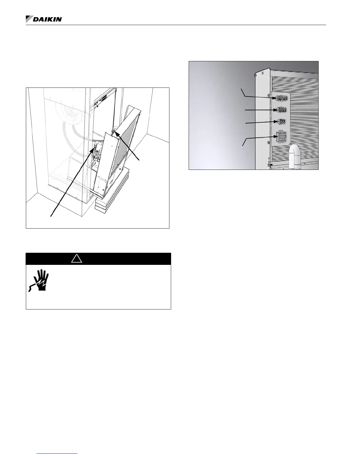
2. Thread the female swivel ends of the hoses on to the
water supply and return connections. Using two crescent
wrenches, one to hold the chassis pipe tting connection
and the second on the exible hose swivel, tighten the
connections. (Figure 35).
Figure 35: Slide chassis into cabinet leaving approximately
a 10" gap for clearance to make flexible hose connections
Supply Connection
Return Connection
Making Cabinet to Chassis Wiring
Connections
DANGER
To avoid electrical shock, personal injury or death:
1. Installer must be qualied, experienced
technician.
2. Disconnect power supply before installation
to prevent electrical shock and damage to
equipment.
!
1. Locate the wires and plugs in the upper fan section of the
unit that connect to the unit chassis.
2. Plug in the wires from the top cabinet section into the
proper molex receptacle on the chassis (Figure 36).
Figure 36: Plug unit component wiring from the top
cabinet section into the proper receptacle on the chassis
(Unit Size 015 Chassis Shown)
Fan Control Receptacle
Main Power Receptacle
Low Voltage
Power Receptacle
Thermostat or Room
Sensor Receptacle
2. Push the chassis into the cabinet until it makes contact
with the stops on the rails at the rear of the cabinet.
Note: Be sure there are no kinks and that the stainless steel
braided hoses do not come in contact with and vibrate on
chassis and cause noise. Also be sure not to pinch wires
between cabinet and chassis when inserting chassis.
Installing the (Optional) Remote Control
Node (RCN) For Use With The Optional
Wireless Thermostat
Heat Pump Kit Part No. 910139783 – Parts Included
1. RCN 3. Wire harness to MTIII Board
2. Bezel with Overlay 4. Wire harness to RCN Board
Introduction
Although the wireless temperature control kit is factory sup-
plied it may also be eld installed, which requires units set up
for unit-mounted 24V thermostat control. The kit consists of a
battery powered wireless remote thermostat and a unit-mounted
Remote Control Node (RCN) and wireless remote control decal.
Note: The Remote Control Node is congured at the factory.
See factory default congurations for Part Number
910139783.
Tools Required
● Phillips head screw driver
● Small Phillips head screw driver
● Small (at head) screw driver
Procedure
1. Be sure that all power to the unit is disconnected and that
the disconnect switch is in the OFF position.
2. Remove the lter and then the front panel/lter rack
(Figure 37).
installation