IM 986-11 • Vertical Stack WSHP 31 www.DaikinApplied.com
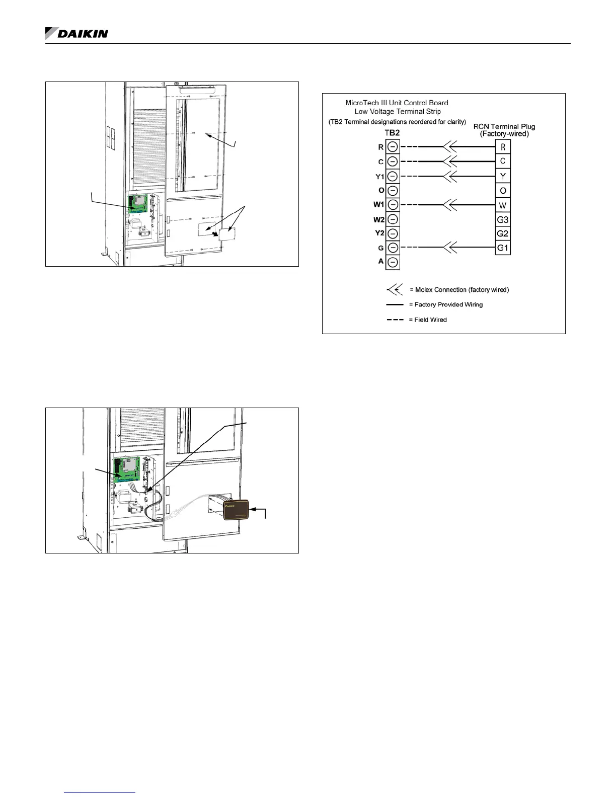
Figure 37: Remove filter and front panel/filter rack
MicroTech III
Unit Controller
Remove front
panel knockout
for RCN board
and bezel
Remove front
panel screws
(10) (Number of
screws may vary,
depending on
unit size)
3. Remove the knockout plate in the front panel/lter rack and cut
away the insulation within the knockout opening (Figure 37).
Note: For clarity, not all unit components are shown in
illustrations.
4. Feed the provided RCN wire harness through the knockout
opening and snap the RCN bezel and board assembly into
the knockout (Figure 38).
Note: Feed RCN wire harness into the control box through
the top wire hole.
Figure 38: Feed RCN wire harness through front panel
knockout
MicroTech III
Unit Controller
Snap-in RCN
board and
bezel into
knockout
Feed RCN
wire harness
into the control
box through
the top wire
hole.
6. Remove existing wires (if any) from the unit control board
terminal plug (TB2), R, C, W, Y, G2.
7. Connect the provided (pre-stripped) RCN wire harness
wires to the unit control board plug on terminals R, C, W, Y
& G2 as shown in Figure 39.
Figure 39: RCN wire harness connections to the MicroTech
III unit controller terminal plug
8. Reinstall the front panel/lter rack and lter.
installation