PerforManCe
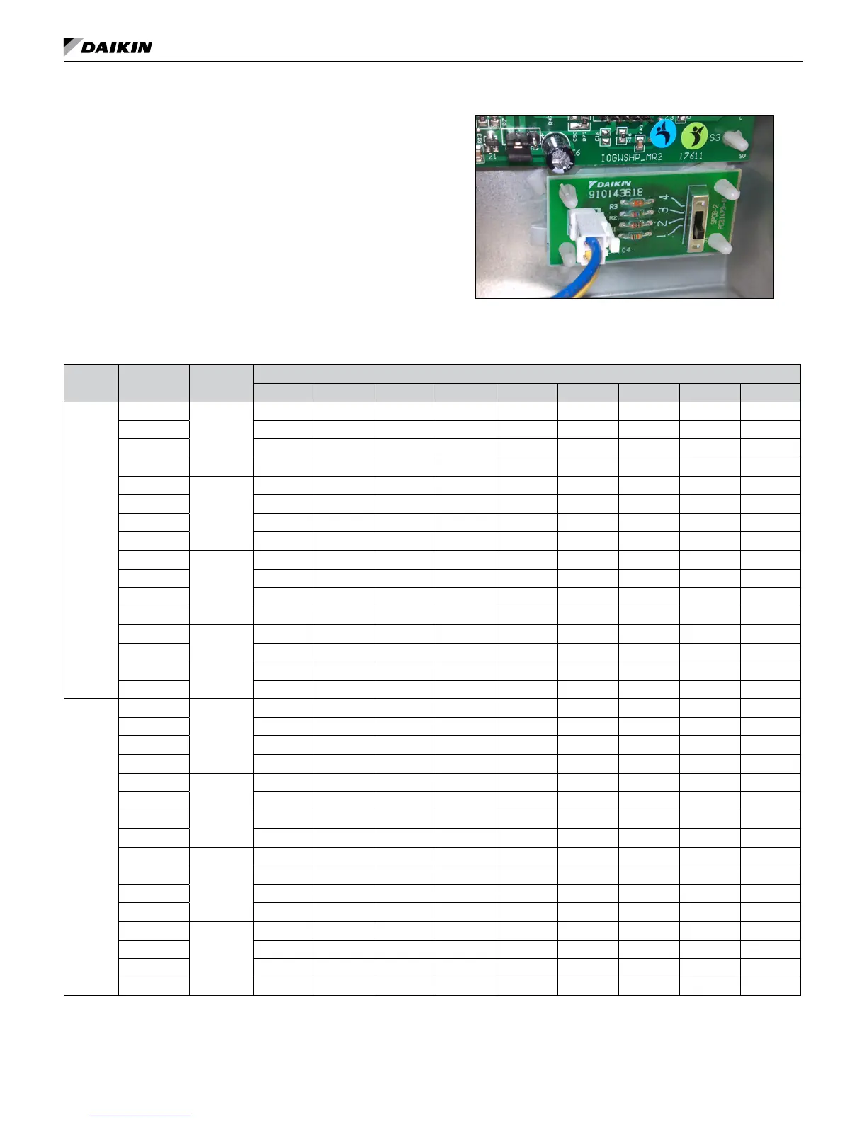
Fan Speed Selector Switch
A 4-position fan speed selector switch located in the control
box allows CFM settings to be eld adjustable. Fan speed
control optimizes unit fan speed based on thermostat/room
sensor inputs. The fan speed switch allows for manually setting
an optimal fan speed specic to the application requirements.
Refer to Table 4
Figure 55: 4-position fan speed selector switch
Fan Performance for Constant Torque EC Motor (Sizes 009-012)
Table 20: Constant torque EC motor CFM values
Unit Size Setting Function
External Static Pressure (in-H
2
O) [Dry Coil and STD Filter) (inches of water column)
0.00 0.05 0.10 0.15 0.20 0.25 0.30 0.35 0.40
009
4 (High)
Stage 1
430 410 390 370 350 340 320 300 280
3 (Standard) 420 400 380 360 340 320 300 270 250
2 (Medium) 350 330 310 290 270 250 230 210 190
1 (Low) 350 330 310 290 270 250 230 210 190
4 (High)
Stage 2
450 430 410 400 380 360 340 320 300
3 (Standard) 430 410 390 370 350 340 320 300 280
2 (Medium) 420 400 380 360 340 320 300 270 250
1 (Low) 350 330 310 290 270 250 230 210 190
4 (High)
Fan Only
350 330 310 290 270 250 230 210 190
3 (Standard) 350 330 310 290 270 250 230 210 190
2 (Medium) 370 340 310 280 250 220 190 160 130
1 (Low) 370 340 310 280 250 220 190 160 130
4 (High)
Hydronic
Heat
430 410 390 370 350 340 320 300 280
3 (Standard) 420 400 380 360 340 320 300 270 250
2 (Medium) 350 330 310 290 270 250 230 210 190
1 (Low) 370 340 310 280 250 220 190 160 130
012
4 (High)
Stage 1
450 430 410 390 370 340 320 300 280
3 (Standard) 420 400 380 360 340 310 290 270 250
2 (Medium) 400 370 350 330 310 290 260 240 220
1 (Low) 400 370 350 330 310 290 260 240 220
4 (High)
Stage 2
470 450 430 410 390 370 350 330 310
3 (Standard) 450 430 410 390 370 340 320 300 280
2 (Medium) 420 400 380 360 340 310 290 270 250
1 (Low) 400 370 350 330 310 290 260 240 220
4 (High)
Fan Only
400 370 350 330 310 290 260 240 220
3 (Standard) 400 370 350 330 310 290 260 240 220
2 (Medium) 360 330 300 270 240 210 180 150 120
1 (Low) 360 330 300 270 240 210 180 150 120
4 (High)
Hydronic
Heat
450 430 410 390 370 340 320 300 280
3 (Standard) 420 400 380 360 340 310 290 270 250
2 (Medium) 400 370 350 330 310 290 260 240 220
1 (Low) 360 330 300 270 240 210 180 150 120
Note: 1. EC motor is programmed to make soft starts and stops to reduce stress transmitted to the fan housing. They adjust their speed and torque to deliver constant
airow over a wide range of external static pressure.
2. Units are shipped at setting 3 (standard). Speed adjustment is done by 4-position switch in the control box.
3. The unit is capable of high-low fan performance through the use of a 2-stage thermostat wired to specic terminals for
High-Low CFM fan performance. Standard operation with a 1-stage thermostat is indicated as stage 2 fan performance.
www.DaikinApplied.com 45 Vertical Stack WSHP • IM 986-11