PerforManCe
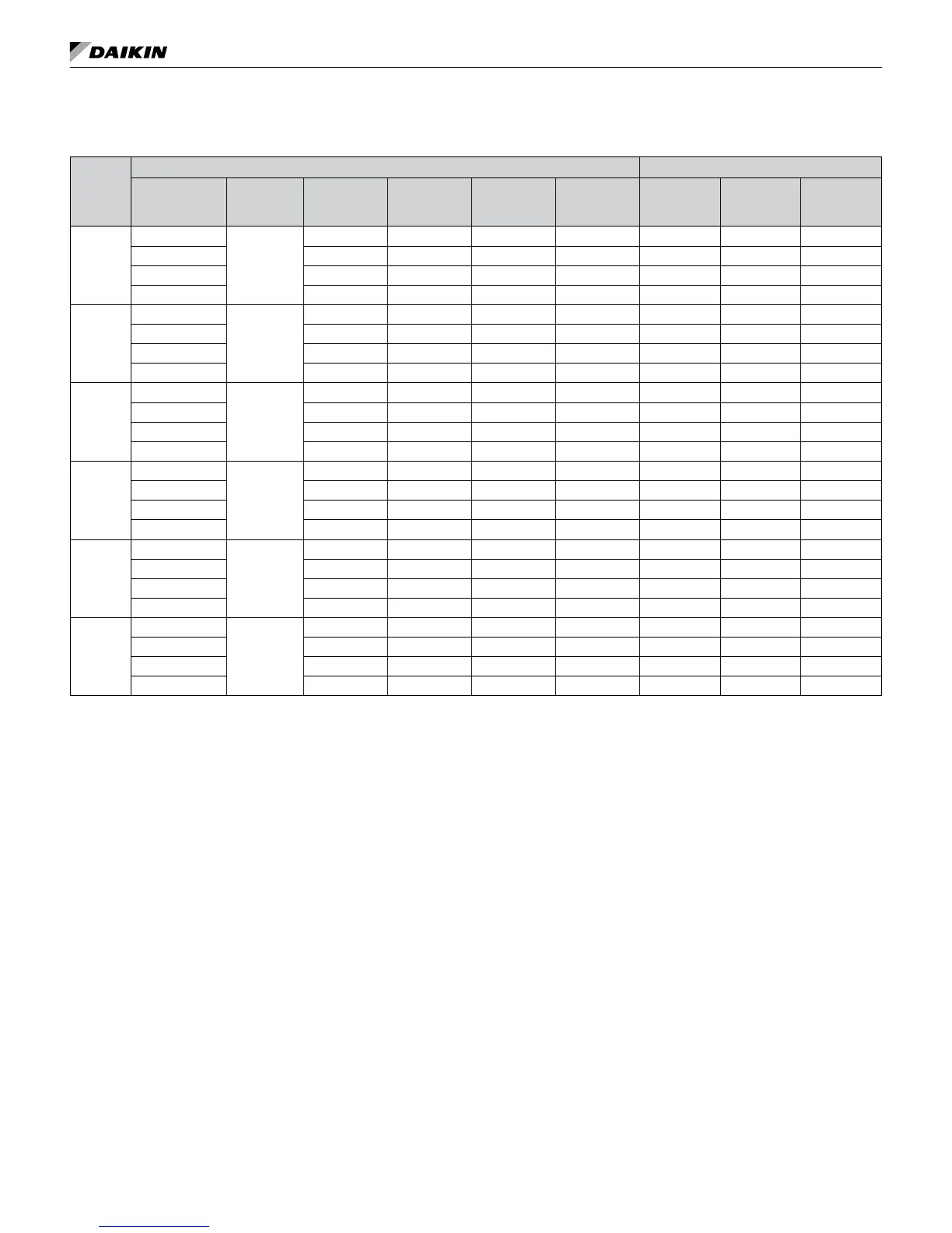
Fan Performance for Constant CFM EC Motor (Sizes 015 - 036)
Table 21: Single stage units with constant CFM EC motor
Unit
Size
MicroTech III Unit Controller
3
I/O Expansion Module
2
Setting
Maximum
ESP
(in. WC.)
1
Low CFM
Heat
1
High CFM
Heat
1
Low CFM
Cool
1
High CFM
Cool
Setting Fan Only
Hydronic
Heat
015
4 (High)
0.40
500 540 500 540 A 500 500
3 (Standard) 440 500 440 500 B 440 440
2 (Medium) 390 440 390 440 C 390 390
1 (Low) 390 390 390 390 D 290 290
018
4 (High)
0.40
600 680 600 680 A 600 600
3 (Standard) 530 600 530 600 B 530 530
2 (Medium) 470 530 470 530 C 470 470
1 (Low) 470 470 470 470 D 360 360
021
4 (High)
0.40
700 770 700 770 A 700 700
3 (Standard) 610 700 610 700 B 610 610
2 (Medium) 530 610 530 610 C 530 530
1 (Low) 530 530 530 530 D 400 400
024
4 (High)
0.40
800 900 800 900 A 800 800
3 (Standard) 700 800 700 800 B 700 700
2 (Medium) 600 700 600 700 C 600 600
1 (Low) 600 600 600 600 D 450 450
030
4 (High)
0.40
1000 1120 1000 1120 A 1000 1000
3 (Standard) 880 1000 880 1000 B 880 880
2 (Medium) 760 880 760 880 C 760 760
1 (Low) 760 760 760 760 D 580 580
036
4 (High)
0.40
1200 1310 1200 1310 A 1200 1200
3 (Standard) 1050 1200 1050 1200 B 1050 1050
2 (Medium) 910 1050 910 1050 C 910 910
1 (Low) 910 910 910 910 D 710 710
Notes:
1
The unit is capable of high-low fan performance through the use of a 2-stage thermostat wired to specic terminals for High-Low CFM.
2
Units are shipped at setting 3 (standard). Fan speed settings may be changed via the 4-position fan speed
selector switch located inside the control box.
3
Refer to Figure 56 on page 47 for location of jumpers JP1 and JP2 on the I/O expansion module. Refer to Table 23 on page 47 for jumper congurations.
IM 986-11 • Vertical Stack WSHP 46 www.DaikinApplied.com