Controls
MicroTech® III SmartSource Unit Controller
The MicroTech III SmartSource unit controller allows thermo-
stat, Daikin sensor and DDC standalone operation. The R
(24VAC) terminal is used to operate thermostat inputs G, Y1,
Y2, W1, W2, W3, W4 and TB1-1. The C (0VAC) terminal is
used to control inputs U, E and O. No external power sources
may be used to operate the MicroTech III controller. All units
must be properly grounded per local code requirements.
For information on sequence of operation and troubleshoot-
ing refer to OM 1149-xx.
NOTICE
Remote Reset of Automatic Lockouts
The Remote Reset feature provides the means to remotely
reset automatic lockouts. There are (3) means to reset an auto-
matic lockout condition:
• Using the thermostat create 2 demands for capacity within
30 seconds
• Press the Room Sensor or Thermostat Timed Override/
Reset Button for more than 10 seconds
• Turn the unit power off
When the cause of the fault condition has been cleared, and
the unit transitions from not requiring any capacity to needing
any capacity twice within 30 seconds (accomplished by user
manipulation of the Heat/Cool/Auto/Off switch on the thermo-
stat), an alarm reset equivalent to a tenant override button re-
set is generated. The intelligent reset counter and the 24 hour
timer are cleared when this type of alarm reset is generated.
Note: This feature only applies to thermostat controlled
systems.
For room sensor controlled units, pressing the “Override” or
“Reset” button for more than 10 seconds will apply a ground
signal to the tenant override in(screw terminal connection at
TB1 pin 4) will clear the lockout alarm once the cause of the
fault condition has been cleared.
A unit power cycle can also be used to clear an automatic lock-
out if the conditions causing the fault have been cleared.
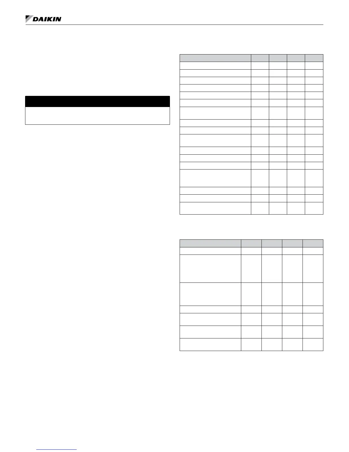
Table 16: MicroTech III SmartSource unit controller fault &
status LED's
Description Type Yellow Green Red
I/O Expansion Communication Fail Fault ON Flash Flash
Invalid Conguration Fault Flash Flash OFF
Low Voltage Brownout Fault OFF Flash OFF
Emergency Shutdown Mode OFF Flash OFF
Compressor High Pressure Fault OFF OFF Flash
Compressor Low Pressure Fault OFF OFF ON
Compressor Suction Temp Sensor
Fail
Fault Flash Flash ON
Compressor Low Suction Temp Fault Flash OFF OFF
Freeze Fault Detect Fault Flash OFF Flash
Room Temp Sensor Fail (Room
Sensor Control Only)
Fault Flash Flash ON
Leaving Water Temp Sensor Fail Fault Flash Flash ON
Condensate Overow Fault ON OFF OFF
Serial EEPROM Corrupted Fault ON ON ON
Waterside Economizer Low Temp
Cutout (WSE Control & Call for
Cooling)
Mode Flash ON Flash
Service Test Mode Enabled Mode Flash Flash Flash
Unoccupied Mode Mode ON ON OFF
Occupied, Bypass, Standby, or
Tenant Override Modes
Mode OFF ON OFF
Note: Mode/faults are listed in order of priority.
Table 17: I/O expansion module fault & status LED's
Description Type Yellow Green Red
Baseboard Communication Fail Fault Flash OFF Flash
Entering Water Temp Sensor
Fail
(Boilerless Electric Heat or
Waterside Economizer Only or
Hydronic Heat)
Fault ON OFF Flash
Low Entering Water
Temperature
(No Display On Boilerless
Electric Heat)
Fault OFF ON Flash
Fan is OFF Mode OFF ON OFF
Fan Running at Low Speed (0
to 33%) Duty Cycle
Mode OFF Flash OFF
Fan Running at Medium Speed
(34 to 66%) Duty Cycle
Mode ON Flash OFF
Fan Running at High Speed (67
to 100%) Duty Cycle
Mode Flash Flash OFF
IM 986-11 • Vertical Stack WSHP 41 www.DaikinApplied.com