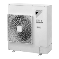
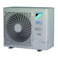
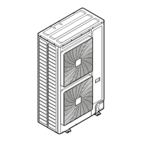
Field Settings for Outdoor Unit (6/8 HP Models) SiAF332111E
130 Part 5 Field Settings and Test Operation
3.5.2 Overview of Monitor Mode (Mode 1)
1: Numbers in the "No." column represent the number of times to press the BS button.
2: Number of indoor units connected: represents the number of indoor units connected to a
single outdoor system.
3: Number of outdoor units: represents the number of outdoor units connected to a single
DIII-NET that is a communication line.
4: Number of terminal units: represents the number of indoor units connected to a single
DIII-NET that is a communication line.
No.
1
Item Contents
Description
Display
Description
Display
SEG
1
SEG
2
SEG
3
SEG
1
SEG
2
SEG
3
1
Low noise operation state
display
1. 0 1
In normal operation
In low noise operation
0
1
2
Demand operation state
display
1. 0 2
In normal operation
In demand operation
0
1
3
Automatic backup
operation setting
1. 0 3
OFF
ON
0
1
5
Te setting
1. 0 5
Normal 6°C
High sensible 7°C
High sensible 8°C
High sensible 9°C
High sensible 10°C
High sensible 11°C
2
3
4
5
6
7
8
Low noise/demand
address
1. 0 8
Possible 0-31
3
0
1
9
AIRNET address
1. 0 9
Possible 0-63
6
0
3
10
Number of connected
indoor units (refer to 2)
1. 1 0
Possible 0-63
6
0
3
13
Number of outdoor units
(refer to 3)
1. 1 3
Possible 0-63
6
0
3
15
Number of units in zone
1. 1 5
Possible 0-63
6
0
3
16
Number of all indoor units
of several systems if “F1F2
OUT/D is wired between
systems (refer to 4)
1. 1 6
Possible 0-128
12
0
8
17 Description of error (latest) 1. 1 7 Refer to information in Error Code via
Outdoor Unit PCB on page 185.
18
Description of error
(1 cycle before)
1. 1 8
19
Description of error
(2 cycles before)
1. 1 9

 Loading...


