Installation
12a
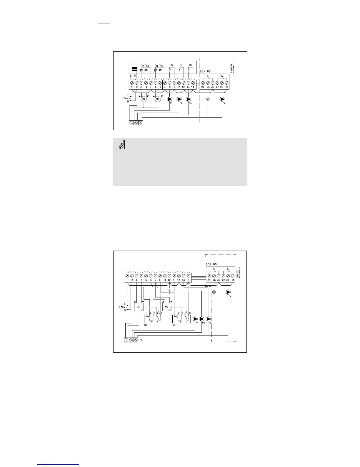
Electrical connections -
230 V a.c. - in general
230 V a.c. connections - without safety thermostat
Optional
P2 / M2*
For the heating systems 2, 4, 5 and 7 it must be determined
whether the actuator is to be controlled by means of the terminals
6 and 7 (M2) or the terminal 11, cf. section 10.
Terminals 6 and 7: Only control valves with 3-point control
Terminal 11: For change-over valves ON / OFF
Establish these jumpers:
1-5-8-10-12-14
and jumper 2 to common N-terminal.
If an ECA 80 module is to be applied, the jumpers 14-26-29
must be established additionally.
230 V a.c. connections - with safety thermostat
Optional
This circuit diagram is only valid if Danfoss actuators are used
Establish these jumpers:
1-10-12-14
Safety thermostat:
4, 5 and 10 with ST- (safety thermostat)
and jumper 2 to common N-terminal.
If an ECA 80 module is to be applied, the jumpers 14-26-29
must be established additionally.

 Loading...