The grey
side of the
ECL Card
Basic set-up
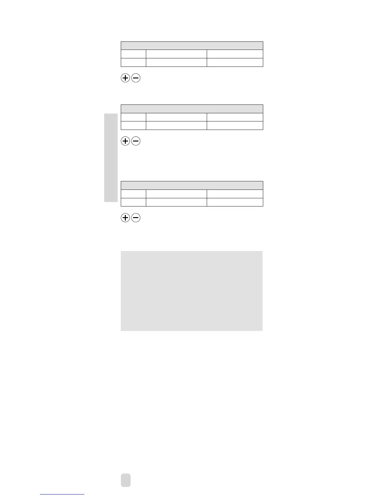
4 Proportional band, Xp
Circuit Setting range Factory setting
I / (II) 1 ... 250 K 80 / (80) K
Set the proportional band.
A higher value will result in a stable but slow
control of the flow temperature.
5 Integration time constant, Tn
Circuit Setting range Factory setting
I / (II) 5 ... 999 sec. 30 / (30) sec.
Set a high integration time constant to obtain a
slow but stable reaction to deviations.
A small integration constant will make the
controller react fast but with less stability
6 Running time of the motorized control valve
Circuit Setting range Factory setting
I / (II) 5 ... 250 sec. 35 / (35) sec.
Set the running time of the motorized control valve
according to the example. This is the time it takes
the controlled unit to move from fully closed to
fully open position.
How to calculate the running time of a motorized
control valve
The running time of the motorized control valve is calculated
using the following methods:
Seated valves
Running time = Valve stroke (mm) x actuator speed (sec. / mm)
Example: 5.0 mm x 15 sec. / mm = 75 sec.
Rotating valves
Running time = Turning degrees x actuator speed (sec. / degr.)
Example: 90 degrees x 2 = 180 sec.
Control parameters -
lines 4-7
26a