3.4.3 Motor Connection
WARNING
INDUCED VOLTAGE!
Run output motor cables from multiple frequency
converters separately. Induced voltage from output
motor cables run together can charge equipment
capacitors even with the equipment turned off and
locked out. Failure to run output motor cables separately
could result in death or serious injury.
•
For maximum cable sizes, see chapter 11.1 Power-
dependent Specifications
•
Comply with local and national electrical codes
for cable sizes
•
Gland plates are provided at the base of IP21/54
and higher (NEMA1/12) units
•
Do not install power factor correction capacitors
between the frequency converter and the motor
•
Do not wire a starting or pole-changing device
between the frequency converter and the motor
•
Connect the 3-phase motor wiring to terminals
96 (U), 97 (V), and 98 (W)
•
Earth (ground) the cable in accordance with the
instructions provided
•
Torque terminals in accordance with the
information provided in chapter 11.3.4 Connection
Tightening Torques
•
Follow motor manufacturer wiring requirements
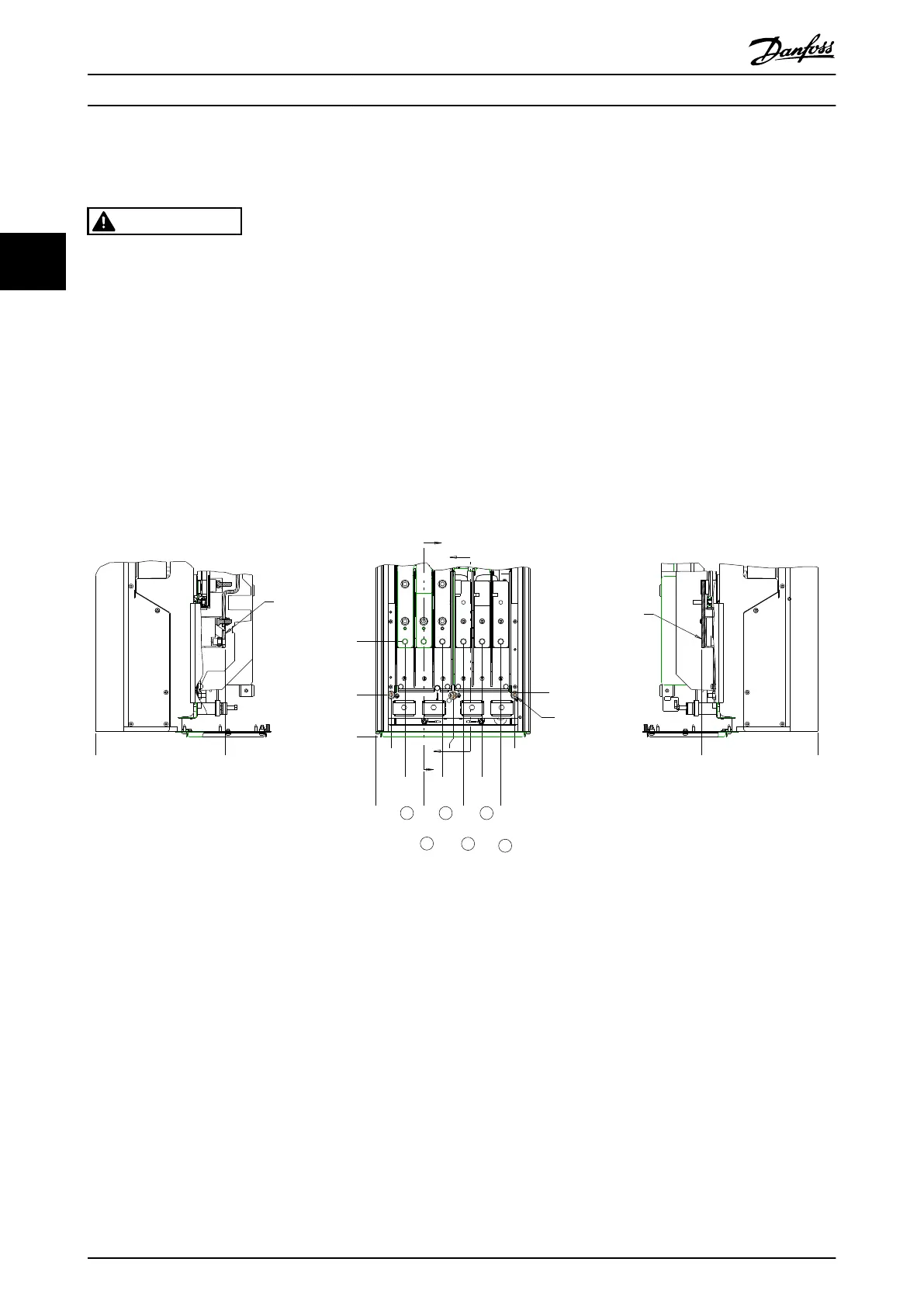
3.4.3.1
Terminal Locations: D1h-D4h
A
A
B
B
33
1.3[ ]
0
0.0[ ]
62
2.4[ ]
101
4.0[ ]
140
5.5[ ]
163
6.4[ ]
185
7.3[ ]
224
8.8[ ]
263
10.4[ ]
293
11.5[ ]
GROUND 88
3.5[ ]
0
0.0[ ]
200
7.9[ ]
94
3.7[ ]
244
9.6[ ]
0
0.0[ ]
272
10.7[ ]
0
0.0[ ]
S
U
W
R T V
3X M8x20 STUD
WITH NUT
SECTION A-A
MAINS TERMINALS
MAINS TERMINAL
SECTION B-B
MOTOR TERMINALS
MOTOR
TERMINAL
130BC305.10
Illustration 3.7 Terminal Locations D1h
Installation Operating Instructions
16 Danfoss A/S © Rev. 06/2014 All rights reserved. MG16D302
33