•
Some options available for ordering with the unit
may provide additional terminals. See the manual
provided with the equipment option.
3.5.5 Wiring to Control Terminals
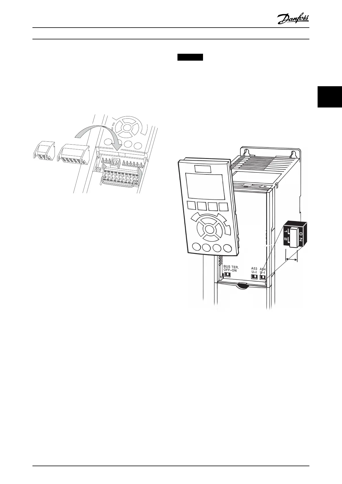
Terminal plugs can be removed for easy access.
Illustration 3.30 Removal of Control Terminals
3.5.6
Control Terminal Functions
Frequency converter functions are commanded by
receiving control input signals.
•
Each terminal must be programmed for the
function it is supporting in the parameters
associated with that terminal. See
chapter 6 Programming and chapter 7 Application
Examples for terminals and associated parameters.
•
It is important to confirm that the control
terminal is programmed for the correct function.
See chapter 6 Programming for details on
accessing parameters and programming.
•
The default terminal programming is intended to
initiate frequency converter functioning in a
typical operational mode.
3.5.6.1
Terminal 53 and 54 Switches
•
Analog input terminals 53 and 54 can select
either voltage (0 to 10 V) or current (0/4-20 mA)
input signals.
•
Remove power to the frequency converter before
changing switch positions.
•
Set switches A53 and A54 to select the signal
type. U selects voltage, I selects current.
•
The switches are accessible when the LCP has
been removed (see Illustration 3.31).
NOTICE
Some option cards available for the unit may cover these
switches and must be removed to change switch
settings. Always remove power to the unit before
removing option cards. Observe the discharge time in
Table 2.1.
•
Terminal 53 default is for a speed reference signal
in open loop, which is set in 16-61 Terminal 53
Switch Setting
•
Terminal 54 default is for a feedback signal in
closed loop, which is set in 16-63 Terminal 54
Switch Setting
Illustration 3.31 Location of Terminals 53 and 54 Switches and
Bus Termination Switch
STO is an option. To run STO, additional wiring for the
frequency converter is required. Refer to VLT
®
Frequency
Converters Safe Torque Off Operating Instructions for further
information.
3.6
Serial Communication
RS-485 is a 2-wire bus interface compatible with multi-drop
network topology, i.e. nodes can be connected as a bus, or
via drop cables from a common trunk line. A total of 32
nodes can be connected to 1 network segment.
Repeaters divide network segments. Each repeater
functions as a node within the segment it is installed in.
Each node connected within a given network must have a
unique node address across all segments.
Installation
Operating Instructions
MG16D302 Danfoss A/S © Rev. 06/2014 All rights reserved. 33
3 3