3.5.1 Access
All terminals to the control cables are located underneath
the LCP on the inside of the frequency converter. To
access, open the door (IP21/54) or remove the front panel
(IP20).
3.5.2 Using Screened Control Cables
Danfoss recommends braided screened/armoured cables to
optimise EMC immunity of the control cables and the EMC
emission from the motor cables.
The ability of a cable to reduce the incoming and
outgoing radiation of electric noise depends on the
transfer impedance (Z
T
). The screen of a cable is normally
designed to reduce the transfer of electric noise; however,
a screen with a lower transfer impedance (Z
T
) value is
more effective than a screen with a higher transfer
impedance (Z
T
).
Transfer impedance (Z
T
) is rarely stated by cable manufac-
turers, but it is often possible to estimate transfer
impedance (Z
T
) by assessing the physical design of the
cable.
Transfer impedance (Z
T
) can be assessed on the basis of
the following factors:
•
The conductibility of the screen material.
•
The contact resistance between the individual
screen conductors.
•
The screen coverage, i.e. the physical area of the
cable covered by the screen - often stated as a
percentage value.
•
Screen type, i.e. braided or twisted pattern.
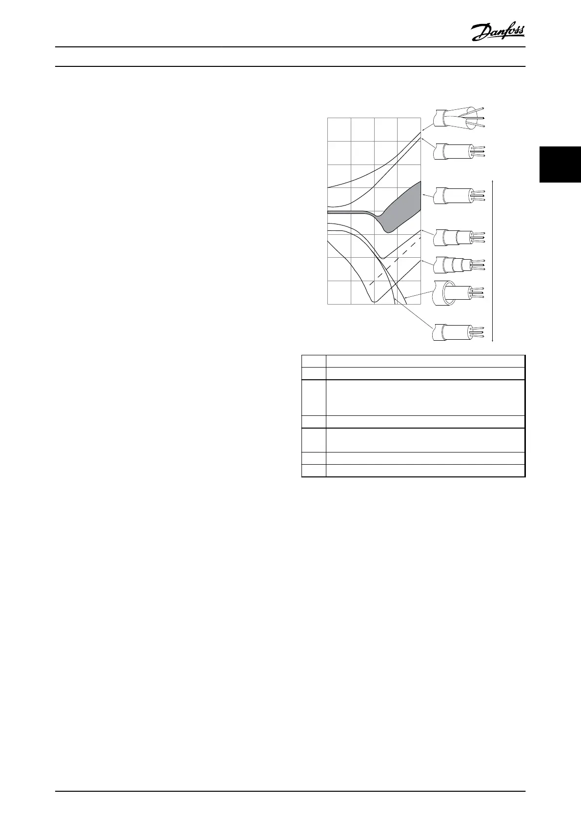
175ZA166.13
0,01 0,1 1 10 100 MHz
10
10
10
1
10
10
10
10
10
a
b
c
d
e
f
g
The lower the Z the better the cable screening performance
Transfer impedance, Z
t
mOhm/m
a
Aluminium-clad with copper wire
b Twisted copper wire or armoured steel wire cable
c Single-layer braided copper wire with varying percentage
screen coverage (this is the typical Danfoss reference
cable).
d Double-layer braided copper wire
e Twin layer of braided copper wire with a magnetic,
screened/armoured intermediate layer
f Cable that runs in copper tube or steel tube
g Lead cable with 1.1 mm wall thickness
Illustration 3.24 Cable Screening Performance
3.5.3
Grounding of Screened Control
Cables
Correct screening
The preferred method in most cases is to secure control
and serial communication cables with screening clamps
provided at both ends to ensure best possible high
frequency cable contact. If the ground potential between
the frequency converter and the PLC is different, electric
noise may occur that disturbs the entire system. Solve this
problem by fitting an equalizing cable next to the control
cable. Minimum cable cross section: 16 mm
2
.
Installation
Operating Instructions
MG16D302 Danfoss A/S © Rev. 06/2014 All rights reserved. 31
3 3