3.4.4 Motor Cable
Connect the motor to terminals U/T1/96, V/T2/97, W/T3/98.
Ground to terminal 99. All types of 3-phase asynchronous
standard motors can be used with a frequency converter
unit. The factory setting is for clockwise rotation with the
frequency converter output connected as follows:
Terminal no. Function
96, 97, 98, Mains U/T1, V/T2, W/T3
99 Ground
Table 3.3 Terminals for Motor Cable Connection
3.4.5
Motor Rotation Check
The direction of rotation can be changed by switching 2
phases in the motor cable, or by changing the setting of
4-10 Motor Speed Direction.
•
Terminal U/T1/96 connected
to U-phase
•
Terminal V/T2/97 connected
to V-phase
•
Terminal W/T3/98
connected to W-phase
175HA036.11
U
1
V
1
W
1
96 97 98
FC
Motor
U
2
V
2
W
2
U
1
V
1
W
1
96 97 98
FC
Motor
U
2
V
2
W
2
Table 3.4 Wiring for Changing Motor Direction
A motor rotation check can be performed using 1-28 Motor
Rotation Check and following the steps shown in the
display.
3.4.6
AC Mains Connection
•
All frequency converters may be used with an
isolated input source as well as with ground
reference power lines. When supplied from an
isolated mains source (IT mains or floating delta)
or TT/TN-S mains with a grounded leg (grounded
delta), set 14-50 RFI Filter to [0] Off. When off, the
internal RFI filter capacitors between the chassis
and the intermediate circuit are isolated. Isolating
the capacitors prevents damage to the
intermediate circuit and reduces ground capacity
currents in accordance with IEC 61800-3.
•
Size wiring is based upon the input current of the
frequency converter.
•
Comply with local and national electrical codes
for cable sizes.
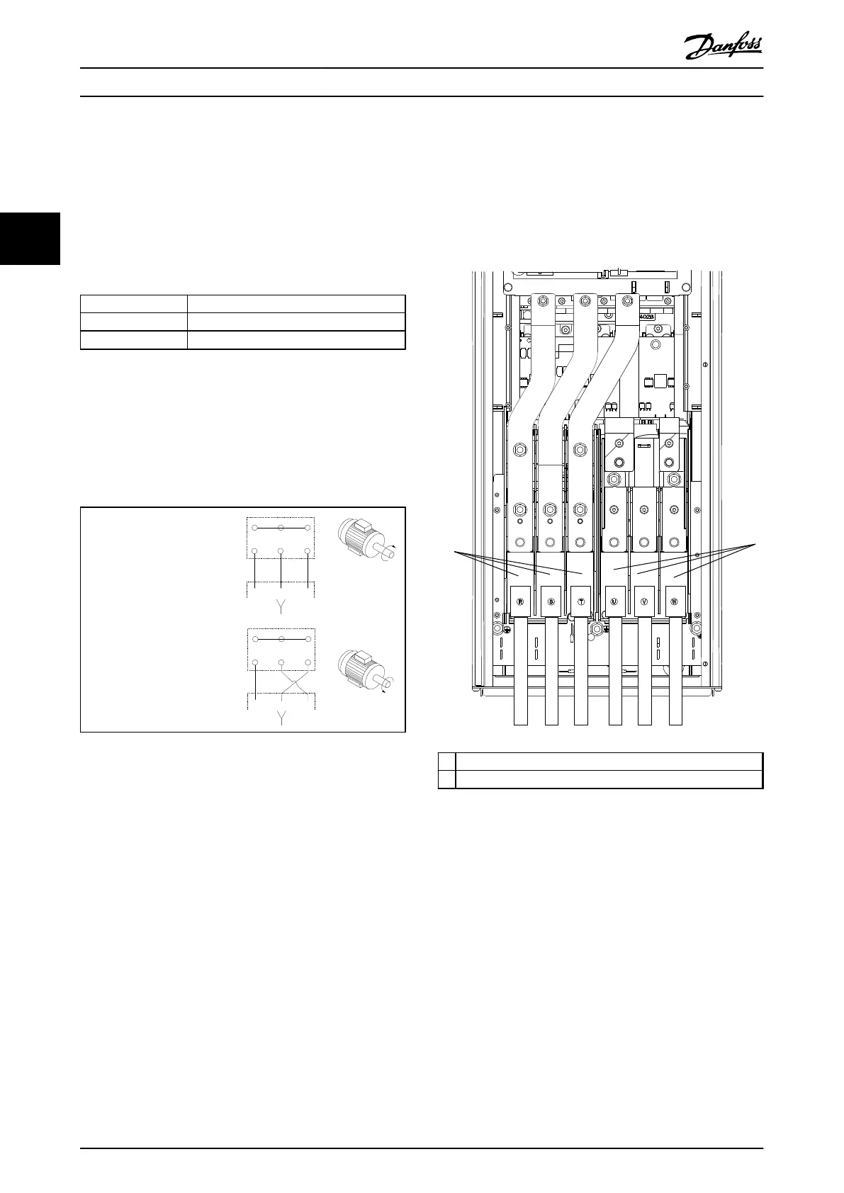
1. Ground the cable in accordance with the
instructions provided.
2. Connect 3-phase AC input power wiring to
terminals L1, L2, and L3 (see Illustration 3.23).
1 Mains connection
2 Motor connection
Illustration 3.23 Connecting to AC Mains
3.5
Control Wiring Connection
•
Isolate control wiring from high power
components in the frequency converter.
•
If the frequency converter is connected to a
thermistor for PELV isolation, optional thermistor
control wiring must be reinforced/double
insulated. A 24 V DC supply voltage is
recommended.
Installation
Operating Instructions
30 Danfoss A/S © Rev. 06/2014 All rights reserved. MG16D302
33