6.3 Control Terminal Programming
Examples
Control terminals can be programmed.
•
Each terminal has specified functions it is capable
of performing.
•
Parameters associated with the terminal enable
the function.
•
For proper frequency converter functioning, the
control terminals must be:
-
Wired properly
-
Programmed for the intended function
-
Receiving a signal
See Table 6.1 for control terminal parameter number and
default setting. (Default setting can change based on the
selection in 0-03 Regional Settings).
The following example shows accessing terminal 18 to see
the default setting.
1. Press [Main Menu] twice, scroll to parameter
group 5-** Digital In/Out Parameter Data Set and
press [OK].
130BT768.10
2-** Brakes
3-** Reference / Ramps
4-** Limits / Warnings
5-** Digital In/Out
14.6% 0.00A 1(1)
Main Menu
Illustration 6.11 Main Menu Display Example
2.
Scroll to parameter group 5-1* Digital Inputs and
press [OK].
130BT769.10
5-0* Digital I/O mode
5-1* Digital Inputs
5-4* Relays
5-5* Pulse Input
14.7% 0.00A 1(1)
Digital In/Out
5-**
Illustration 6.12 Parameter Group Display Example
3.
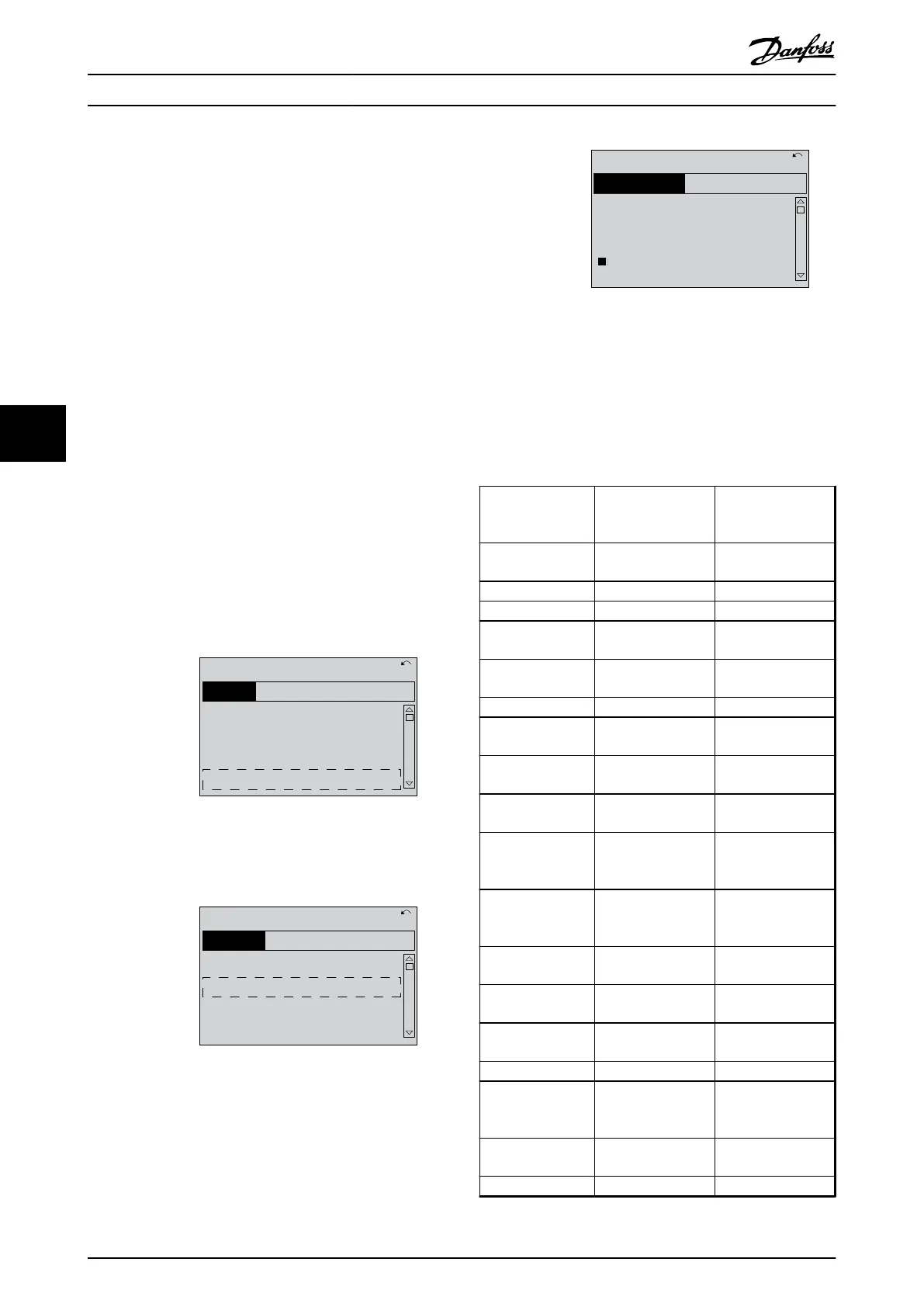
Scroll to 5-10 Terminal 18 Digital Input. Press [OK]
to access function choices. The default setting
Start is shown.
5-1*
130BT770.10
5-10 Terminal 18 Digital
Input
[
8
]] Start
14.7% 0.00A 1(1)
Digital Inputs
Illustration 6.13 Function Choice Display Example
6.4 International/North American Default
Parameter Settings
Setting 0-03 Regional Settings [0] International or [1] North
America changes the default settings for some parameters.
Table 6.1 lists those parameters that are affected.
Parameter International default
parameter value
North American
default parameter
value
0-03 Regional
Settings
International North America
0-71 Date Format DD-MM-YYYY MM/DD/YYYY
0-72 Time Format 24 h 12 h
1-20 Motor Power
[kW]
See Note 1 See Note 1
1-21 Motor Power
[HP]
See Note 2 See Note 2
1-22 Motor Voltage 230 V/400 V/575 V 208 V/460 V/575 V
1-23 Motor
Frequency
50 Hz 60 Hz
3-03 Maximum
Reference
50 Hz 60 Hz
3-04 Reference
Function
Sum External/Preset
4-13 Motor Speed
High Limit [RPM]
See Note 3
1500 RPM 1800 RPM
4-14 Motor Speed
High Limit [Hz]
See Note 4
50 Hz 60 Hz
4-19 Max Output
Frequency
100 Hz 120 Hz
4-53 Warning Speed
High
1500 RPM 1800 RPM
5-12 Terminal 27
Digital Input
Coast inverse External interlock
5-40 Function Relay Alarm No alarm
6-15 Terminal 53
High Ref./Feedb.
Value
50 60
6-50 Terminal 42
Output
Speed 0-HighLim Speed 4-20 mA
14-20 Reset Mode
Manual reset Infinite auto reset
Programming Operating Instructions
46 Danfoss A/S © Rev. 06/2014 All rights reserved. MG16D302
66