FC 300 Instruction Manual
How to Install
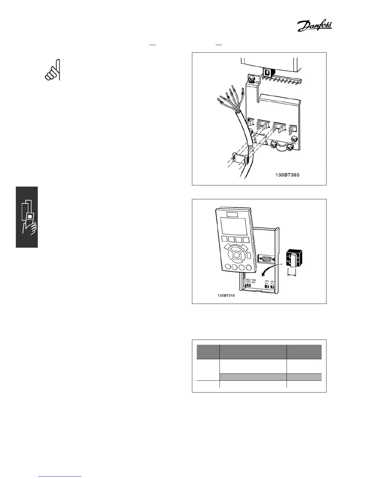
NOTE
Control cables must be shielded/armored.
1. Use a clamp from the accessory bag to
connect the shield to the FC 300 grounding
plate for control cables.
See section entitled Grounding of Shielded/Armored
Control Cables for the correct termination
of contr ol cables.
" Switches S201, S202, and S801
Switches S201 (A53 ) and S202 (A54) are used
to select a current (0-20 mA) or a voltag e
(-10 to 10 V) configuration of the analog input
terminals 53 and 54 respectively.
Switch S801 (BUS TER.) can be used to
enable termination on the RS-485 p
ort
(terminals 68 and 69).
See drawing Diagram showing all electrical
terminals in section Electrical Installa tion.
Default setting:
S201 (A53) = OFF (voltage input)
S202 (A54) = OFF (voltage
input)
S801 (Bus termination) = OF F
" Tightening torques
Tighten powe r, electrical, brake, and ground
terminals with the following torques:
FC 300 Connections Torque
(Nm)
Motor, electrical supply,
brake, DC Bu
s
0.5-0.6
Ground, 24 DC 2-3
Relay, DC filter feedback 0.5-0.6
28
MG.33.A6.22 - VLT is a registered Danfoss trademark
 Loading...


