FC 300 Instruction Manual
How to Install
" Additional Connections
" ControlofMechanicalBrake
Control an electromechanical brake in hoisting/lowering app lications.
• Control the brake using any relay output or digital output (terminal 27 or 29).
• Keep the output closed (voltage-free) as long as the adjustable frequency drive is unable to
"support" the motor, for example due to the load being too heavy.
• Select Mechanical brake control [32] in par. 5-4* for applications with an electromechanical brake.
• The brake is released wh en the motor current exceeds the preset value in par. 2-20.
• The brake is engaged when the output frequency is less than the frequency set in par. 2-21 or
2-22, and only if the adjustable frequency drive carries out a stop command.
If the adjustable f requency drive is in alarm mode or in an overvoltage situation, the
mechanical brake immediately cuts in.
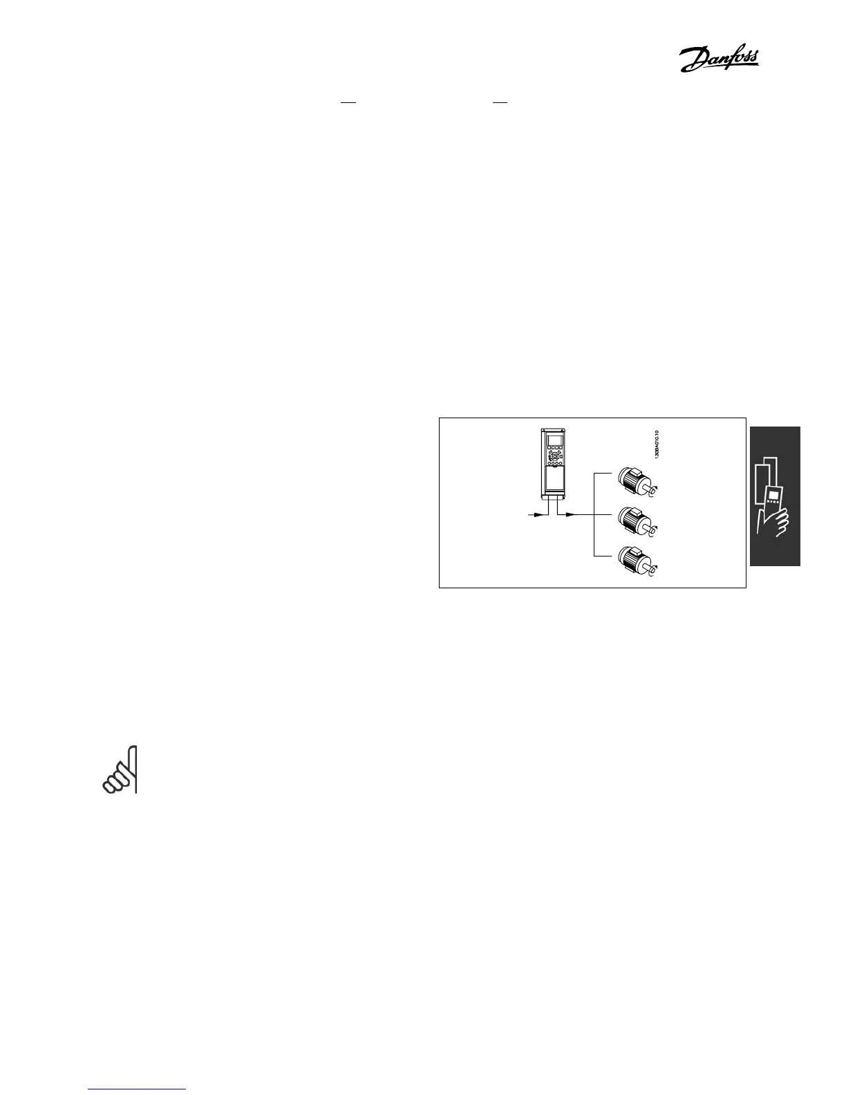
" Parallel con nect ion of motors
The F C 300 is able to control several
parallel-connected motors. The total current
consumption of the motors must not e xceed the
rated output current I
INV
for the FC 300.
Problems may arise at start and at low RPM val
ues if motor sizes are widely different because small motors’
relatively high ohm ic resistance in the stator calls for a higher voltage at start and at low rpm values.
The electronic thermal relay (ETR) of the FC 300 cannot be used as motor protection for the individual motor
in syste m s with motors connected in parallel. Further motor protection must be provided, e.g. thermistors
in each motor or individual therm al
relays. (Circuit bre akers are not suitable as protection).
NOTE
When motors are connected in parallel, parameter 1-02 Automatic m otor adaptation (AMA) cannot
be used and Parameter 1-01 Torque characteristics must be se t to Special motor characteris tics.
For more information, see VLT AutomationDrive FC 300 Design Guide.
" Motor Thermal Protection
The electronic thermal relay in FC 300 has received the UL-approval for single motor protection,
when par. 1-90 Motor Thermal Pr otection is set for ETR Trip and par. 1-2 4 Motor current,
I
M,N
is set to the rated
motor current (see motor name plate).
31
MG.33.A6.22 - VLT is a registered Danfoss trademark

 Loading...


