FC 300 CANopen
12 MG.33.J1.02 VER. 050301 – VLT is a registered Danfoss trademark
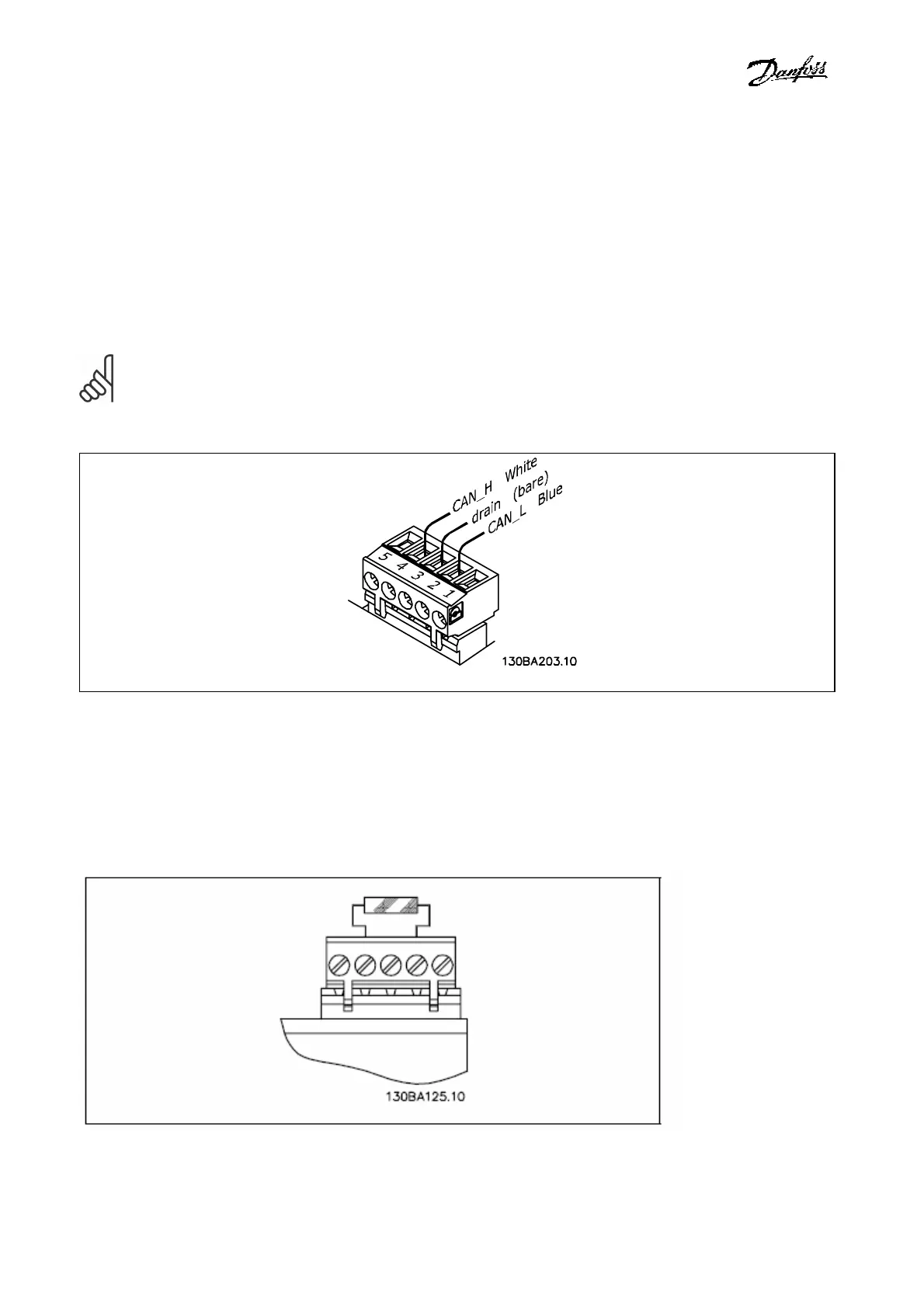
CANopen Connection
It is essential to terminate the bus line properly. A mismatch of impedance may result in reflections on the
line that will corrupt data transmission. The CANopen control card is provided with a plug-cable connector.
When a plug connector is used as a splice between two trunk lines, the removal of devices will not sever the
network. If required, the developer must provide strain relief. In current installations of this type of
connector, the strain relief is attached to the product.
NB!: Install wires only when the network is inactive. This will prevent problems such as shorting the
network supply or disrupting communications.
CANopen Termination
Termination resistors should be installed at each end of the bus line. The resistors must be mounted
between terminal 2 (CAN_L) and terminal 4 (CAN_H) and should have the following specification:
120 Ohm, 1 % Metal film, 1/4 Watt

 Loading...


