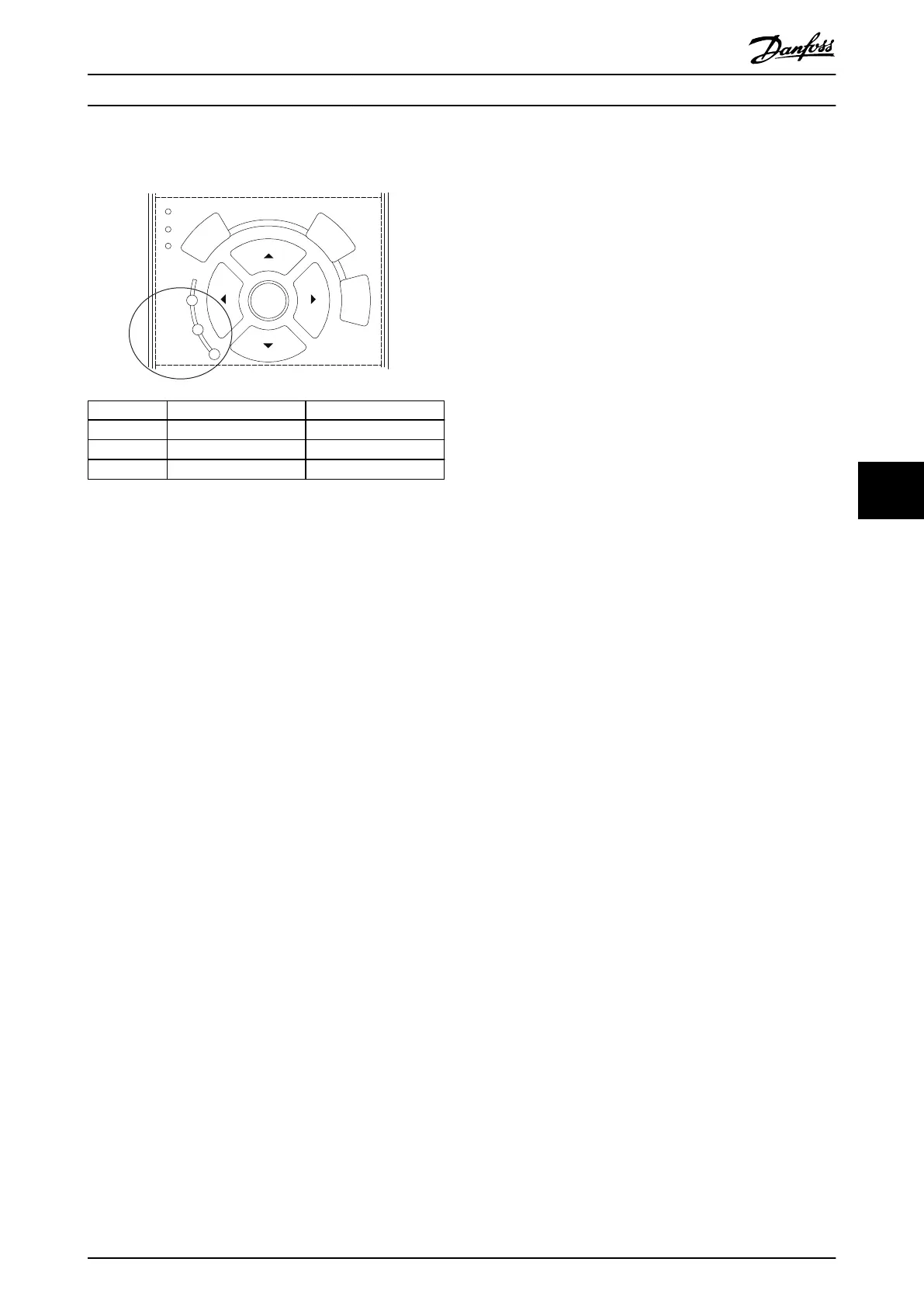
In addition to the text and alarm code in the LCP there are
3 status indicator lights.
Back
Cancel
Info
OK
On
Alarm
Warn.
130BB467.11
Warning indicator light Alarm indicator light
Warning On O
Alarm O On (ashing)
Trip lock On On (ashing)
Illustration 7.2 Status Indicator Lights
7.3 List of Warnings and Alarms
The following warning and alarm information denes each
warning or alarm condition, provides the probable cause
for the condition, and details a remedy or troubleshooting
procedure.
WARNING 1, 10 Volts low
The control card voltage is less than 10 V from terminal 50.
Remove some of the load from terminal 50, as the 10 V
supply is overloaded. Maximum 15 mA or minimum 590 Ω.
A short circuit in a connected potentiometer or incorrect
wiring of the potentiometer can cause this condition.
Troubleshooting
•
Remove the wiring from terminal 50. If the
warning clears, the problem is with the wiring. If
the warning does not clear, replace the control
card.
WARNING/ALARM 2, Live zero error
This warning or alarm only appears if programmed by the
user in parameter 6-01 Live Zero Timeout Function. The
signal on 1 of the analog inputs is less than 50% of the
minimum value programmed for that input. Broken wiring
or faulty device sending the signal can cause this
condition.
Troubleshooting
Check connections on all the analog input
terminals. Control card terminals 53 and 54 for
signals, terminal 55 common. VLT
®
General
Purpose I/O MCB 101 terminals 11 and 12 for
signals, terminal 10 common. VLT
®
Analog I/O
MCB 109 terminals 1, 3, 5 for signals, terminals 2,
4, 6 common.
Check that the frequency converter programming
and switch settings match the analog signal type.
Perform Input Terminal Signal Test.
WARNING/ALARM 3, No motor
No motor is connected to the output of the frequency
converter.
WARNING/ALARM 4, Mains phase loss
A phase is missing on the supply side, or the mains
voltage imbalance is too high. This message also appears
for a fault in the input rectier. Options are programmed in
parameter 14-12 Response to Mains Imbalance.
Troubleshooting
•
Check the supply voltage and supply currents to
the frequency converter.
WARNING 5, DC link voltage high
The DC-link voltage is higher than the high-voltage
warning limit. The limit depends on the frequency
converter voltage rating. The unit is still active.
WARNING 6, DC link voltage low
The DC-link voltage is lower than the low-voltage warning
limit. The limit depends on the frequency converter
voltage rating. The unit is still active.
WARNING/ALARM 7, DC overvoltage
If the DC-link voltage exceeds the limit, the frequency
converter trips after some time.
Troubleshooting
•
Connect a brake resistor.
•
Extend the ramp time.
•
Change the ramp type.
•
Activate the functions in parameter 2-10 Brake
Function.
•
Increase parameter 14-26 Trip Delay at Inverter
Fault.
WARNING/ALARM 8, DC under voltage
If the DC-link voltage drops below the undervoltage limit,
the frequency converter checks if a 24 V DC back-up
supply is connected. If no 24 V DC back-up supply is
connected, the frequency converter trips after a xed time
delay. The time delay varies with unit size.
Troubleshooting
•
Check that the supply voltage matches the
frequency converter voltage.
•
Perform an input voltage test.
•
Perform a soft charge circuit test.
Maintenance, Diagnostics, a... Operating Guide
MG33AT02 Danfoss A/S © 05/2018 All rights reserved. 23
7 7