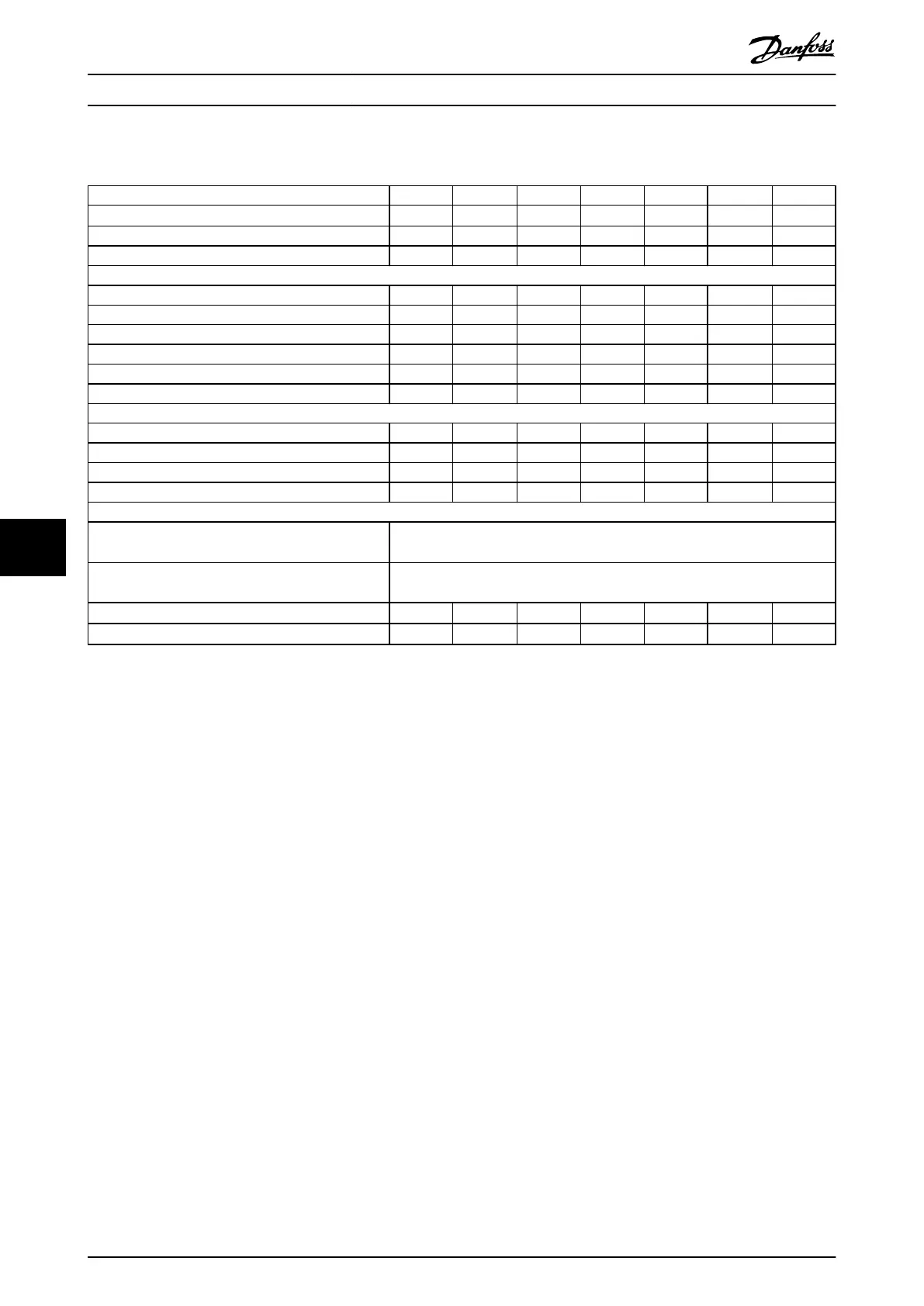
8.1.4 Mains Supply 525–690 V (FC 302 only)
Type designation P1K1 P1K5 P2K2 P3K0 P4K0 P5K5 P7K5
High/normal overload
1)
HO/NO HO/NO HO/NO HO/NO HO/NO HO/NO HO/NO
Typical shaft output [kW/(hp)] 1.1 (1.5) 1.5 (2.0) 2.2 (3.0) 3.0 (4.0) 4.0 (5.0) 5.5 (7.5) 7.5 (10)
Enclosure protection rating IP20 A3 A3 A3 A3 A3 A3 A3
Output current
Continuous (525–550 V) [A] 2.1 2.7 3.9 4.9 6.1 9.0 11.0
Intermittent (525–550 V) [A] 3.4 4.3 6.2 7.8 9.8 14.4 17.6
Continuous (551–690 V) [A] 1.6 2.2 3.2 4.5 5.5 7.5 10.0
Intermittent (551–690 V) [A] 2.6 3.5 5.1 7.2 8.8 12.0 16.0
Continuous kVA 525 V 1.9 2.5 3.5 4.5 5.5 8.2 10.0
Continuous kVA 690 V 1.9 2.6 3.8 5.4 6.6 9.0 12.0
Maximum input current
Continuous (525–550 V) [A] 1.9 2.4 3.5 4.4 5.5 8.1 9.9
Intermittent (525–550 V) [A] 3.0 3.9 5.6 7.0 8.8 12.9 15.8
Continuous (551–690 V) [A] 1.4 2.0 2.9 4.0 4.9 6.7 9.0
Intermittent (551–690 V) [A] 2.3 3.2 4.6 6.5 7.9 10.8 14.4
Additional specications
Maximum cable cross-section
2),5)
for mains, motor,
brake, and load sharing [mm
2
] ([AWG])
4, 4, 4 (12, 12, 12) (minimum 0.2 (24)
Maximum cable cross-section
2),5)
for disconnect [mm
2
]
([AWG])
6, 4, 4 (10, 12, 12)
Estimated power loss at rated maximum load (W)
3)
44 60 88 120 160 220 300
Eciency
4)
0.96 0.96 0.96 0.96 0.96 0.96 0.96
Table 8.10 A3 Enclosure, Mains Supply 525–690 V IP20/Protected Chassis, P1K1–P7K5
Specications
VLT
®
AutomationDrive FC 301/302
40 Danfoss A/S © 05/2018 All rights reserved. MG33AT02
88