For more information about EMC, see chapter 4.2 EMC-compliant Installation
NOTICE
EMC INTERFERENCE
Use shielded cables for motor and control wiring, and
separate cables for input power, motor wiring, and
control wiring. Failure to isolate power, motor, and
control cables can result in unintended behavior or
reduced performance. Minimum 200 mm (7.9 in)
clearance is required between power, motor, and control
cables.
4.5 Motor Connection
WARNING
INDUCED VOLTAGE
Induced voltage from output motor cables that run
together can charge equipment capacitors, even with the
equipment turned o and locked out. Failure to run
output motor cables separately or use shielded cables
could result in death or serious injury.
•
Run output motor cables separately, or
•
Use shielded cables.
•
Comply with local and national electrical codes
for cable sizes. For maximum wire sizes, see
chapter 8.1 Electrical Data.
•
Follow motor manufacturer wiring requirements.
•
Motor wiring knockouts or access panels are
provided at the base of IP21 (NEMA1/12) and
higher units.
•
Do not wire a starting or pole-changing device
(for example Dahlander motor or slip ring
asynchronous motor) between the frequency
converter and the motor.
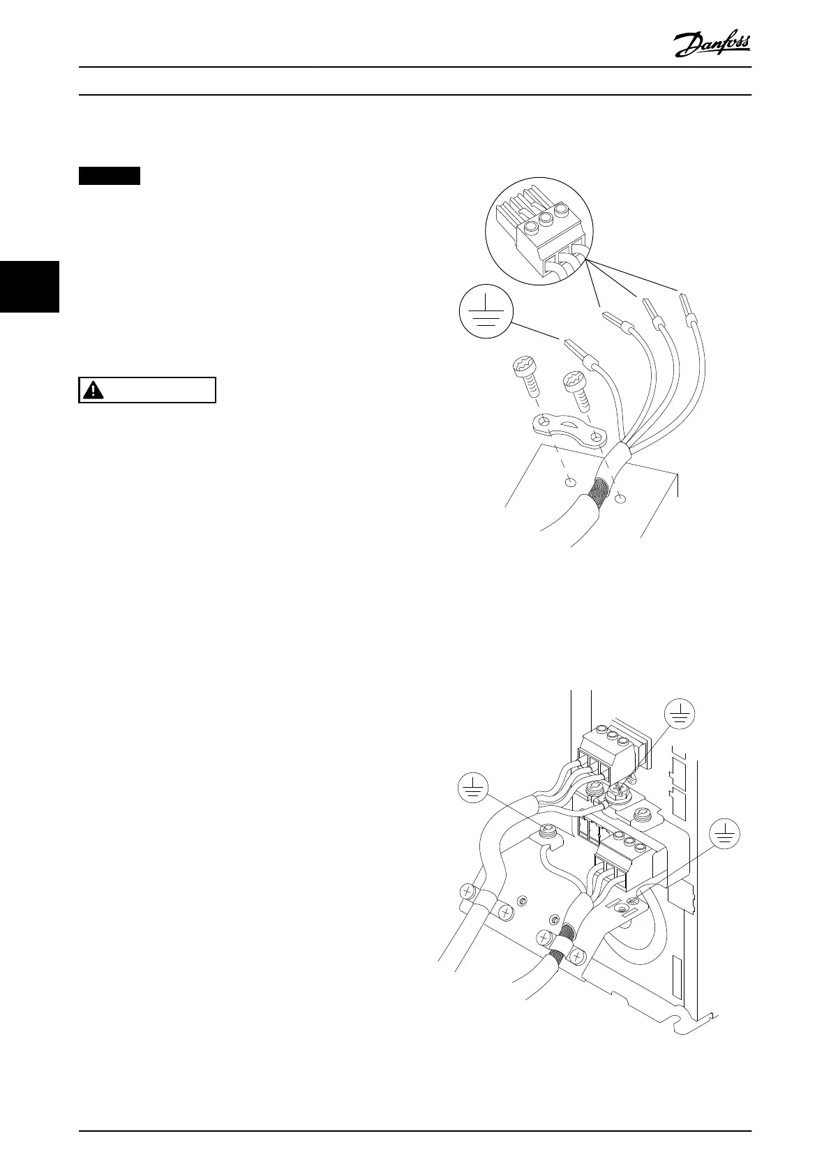
Procedure for grounding the cable shield
1. Strip a section of the outer cable insulation.
2. Position the stripped wire under the cable clamp
to establish mechanical xation and electrical
contact between the cable shield and ground.
3. Connect the ground wire to the nearest
grounding terminal in accordance with the
grounding instructions provided in
chapter 4.3 Grounding, see Illustration 4.4.
4. Connect the 3-phase motor wiring to terminals
96 (U), 97 (V), and 98 (W), see Illustration 4.4.
5. Tighten the terminals in accordance with the
information provided in chapter 8.8 Connection
Tightening Torques.
Illustration 4.4 Motor Connection
Illustration 4.5 shows mains input, motor, and grounding
for basic frequency converters. Actual congurations vary
with unit types and optional equipment.
Illustration 4.5 Example of Motor, Mains, and Ground Wiring
Electrical Installation
VLT
®
AutomationDrive FC 301/302
14 Danfoss A/S © 05/2018 All rights reserved. MG33AT02
44