4.6 AC Mains Connection
•
Size the wiring based on the input current of the
frequency converter. For maximum wire sizes, see
chapter 8.1 Electrical Data.
•
Comply with local and national electrical codes
for cable sizes.
Procedure
1. Connect the 3-phase AC input power wiring to
terminals L1, L2, and L3 (see Illustration 4.5).
2. Depending on the conguration of the
equipment, connect the input power to the
mains input terminals or the input disconnect.
3. Ground the cable in accordance with the
grounding instructions provided in
chapter 4.3 Grounding.
4. When supplied from an isolated mains source (IT
mains or oating delta) or TT/TN-S mains with a
grounded leg (grounded delta), ensure that
parameter 14-50 RFI Filter is set to [0] O. This
setting prevents damage to the DC link and
reduces ground capacity currents in accordance
with IEC 61800-3.
4.7
Control Wiring
•
Isolate the control wiring from the high-power
components in the frequency converter.
•
When the frequency converter is connected to a
thermistor, ensure that the thermistor control
wiring is shielded and reinforced/double
insulated. A 24 V DC supply voltage is
recommended.
4.7.1 Safe Torque O (STO)
To run STO, more wiring for the frequency converter is
required. Refer to VLT
®
Frequency Converters Safe Torque O
Operating Guide for further information.
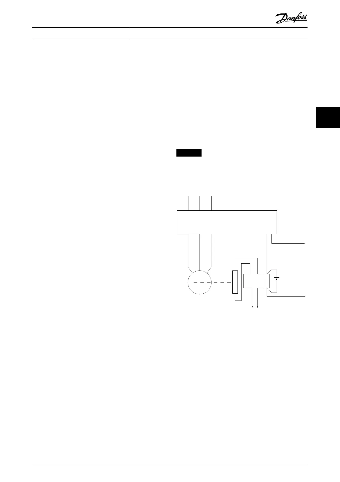
4.7.2 Mechanical Brake Control
In hoisting/lowering applications, it is necessary to
control an electro-mechanical brake.
•
Control the brake using any relay output or
digital output (terminal 27 or 29).
•
Keep the output closed (voltage-free) as long as
the frequency converter is unable to keep the
motor at standstill, for example due to the load
being too heavy.
•
Select [32] Mechanical brake control in parameter
group 5-4* Relays for applications with an electro-
mechanical brake.
•
The brake is released when the motor current
exceeds the value in parameter 2-20 Release Brake
Current.
•
The brake is engaged when the output frequency
is less than the frequency set in
parameter 2-21 Activate Brake Speed [RPM] or
parameter 2-22 Activate Brake Speed [Hz], and only
if the frequency converter carries out a stop
command.
If the frequency converter is in alarm mode or in an
overvoltage situation, the mechanical brake immediately
closes.
NOTICE
The frequency converter is not a safety device. It is the
responsibility of the system designer to integrate safety
devices according to relevant national crane/lift
regulations.
130BA902.10
L1 L2 L3
U V W
02 01
A1
A2
Frequency converter
Output
relay
Command circuit
220 V AC
Mechanical
brake
Shaft
Motor
Freewheeling
diode
Brake
380 V AC
Output
contactor
input
power circuit
Illustration 4.6 Connecting the Mechanical Brake to the
Frequency Converter
Electrical Installation Operating Guide
MG33AT02 Danfoss A/S © 05/2018 All rights reserved. 15
4 4