e30bf228.11
L1
L2
L3
PE
PE
u
v
w
2
1
3
5
16
17
18
14
12
8
7
10
9
4
11
13
4
6
15
90
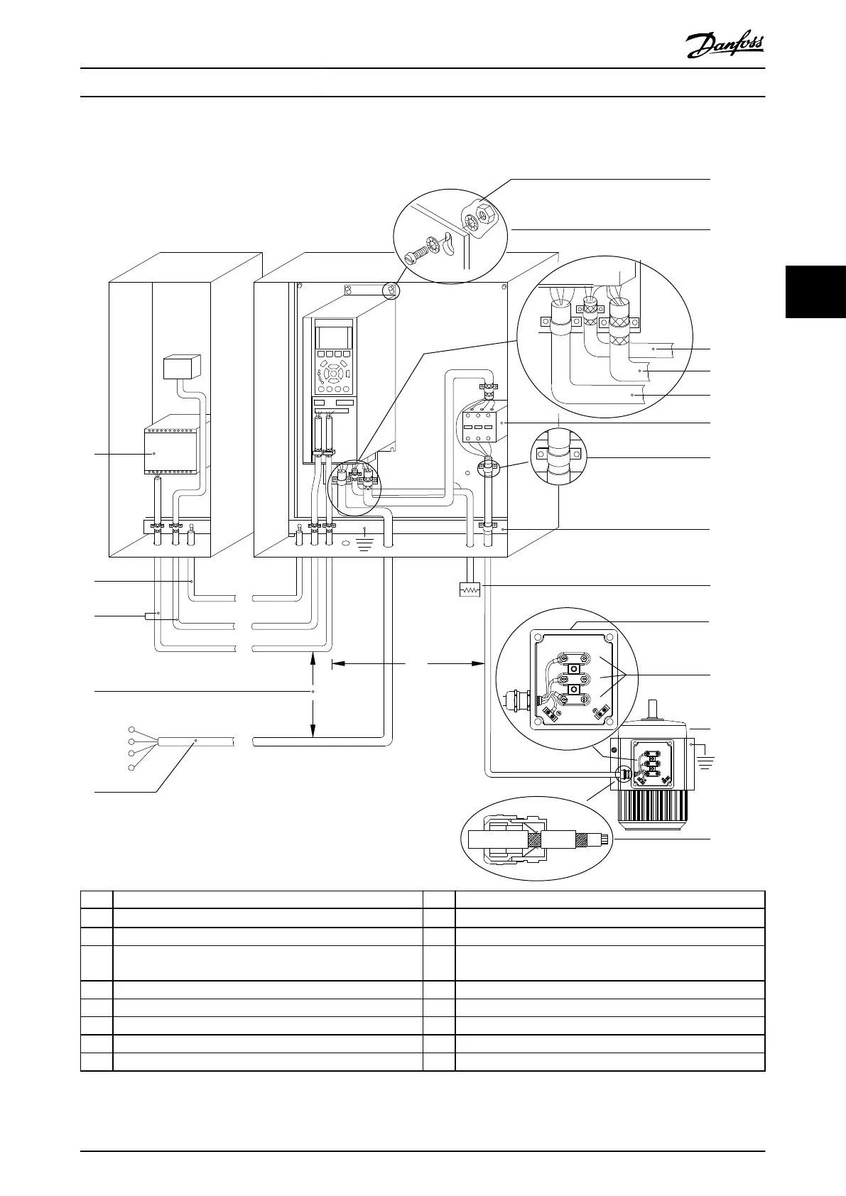
1 PLC. 10 Mains cable (unshielded).
2
Minimum 16 mm
2
(6 AWG) equalizing cable.
11 Output contactor.
3 Control cables. 12 Cable insulation stripped.
4 Minimum 200 mm (7.9 in) between control cables, motor
cables, and mains cables.
13 Common ground busbar. Follow local and national
requirements for cabinet grounding.
5 Mains supply. 14 Brake resistor.
6 Bare (unpainted) surface. 15 Metal box.
7 Star washers. 16 Connection to motor.
8 Brake cable (shielded). 17 Motor.
9 Motor cable (shielded). 18 EMC cable gland.
Illustration 4.3 Example of Proper EMC Installation
Electrical Installation Operating Guide
MG33AT02 Danfoss A/S © 05/2018 All rights reserved. 13
4 4
 Loading...


