2) Except STO input terminal 37.
STO terminal 37
1, 2)
(terminal 37 is xed PNP logic)
Voltage level 0–24 V DC
Voltage level, logic 0 PNP <4 V DC
Voltage level, logic 1 PNP >20 V DC
Maximum voltage on input 28 V DC
Typical input current at 24 V 50 mA rms
Typical input current at 20 V 60 mA rms
Input capacitance 400 nF
All digital inputs are galvanically isolated from the supply voltage (PELV) and other high-voltage terminals.
1) See chapter 4.7.1 Safe Torque O (STO) for further information about terminal 37 and STO.
2) When using a contactor with a DC coil inside in combination with STO, it is important to make a return way for the current
from the coil when turning it o. This can be done by using a freewheel diode (or, alternatively, a 30 V or 50 V MOV for quicker
response time) across the coil. Typical contactors can be bought with this diode.
Analog inputs
Number of analog inputs 2
Terminal number 53, 54
Modes Voltage or current
Mode select Switch S201 and switch S202
Voltage mode Switch S201/switch S202 = OFF (U)
Voltage level -10 V to +10 V (scaleable)
Input resistance, R
i
Approximately 10 kΩ
Maximum voltage ±20 V
Current mode Switch S201/switch S202 = ON (I)
Current level 0/4 to 20 mA (scaleable)
Input resistance, R
i
Approximately 200 Ω
Maximum current 30 mA
Resolution for analog inputs 10 bit (+ sign)
Accuracy of analog inputs Maximum error 0.5% of full scale
Bandwidth 100 Hz
The analog inputs are galvanically isolated from the supply voltage (PELV) and other high-voltage terminals.
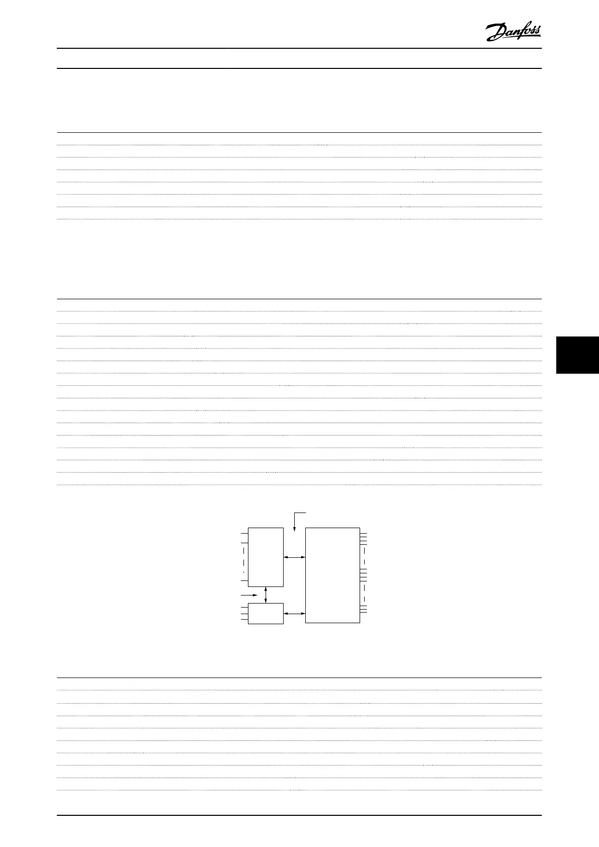
Mains
Functional
isolation
PELV isolation
Motor
DC-bus
High
voltage
Control
+24 V
RS485
18
37
130BA117.10
Illustration 8.1 PELV Isolation
Pulse/encoder inputs
Programmable pulse/encoder inputs 2/1
Terminal number pulse/encoder 29
1)
, 33
2)
/32
3)
, 33
3)
Maximum frequency at terminal 29, 32, 33 110 kHz (Push-pull driven)
Maximum frequency at terminal 29, 32, 33 5 kHz (Open collector)
Minimum frequency at terminal 29, 32, 33 4 Hz
Voltage level See parameter group 5-1* Digital Inputs in the programming guide.
Maximum voltage on input 28 V DC
Input resistance, R
i
Approximately 4 kΩ
Pulse input accuracy (0.1–1 kHz) Maximum error: 0.1% of full scale
Specications Operating Guide
MG33AT02 Danfoss A/S © 05/2018 All rights reserved. 45
8 8