58 | © Danfoss | August 2018 AQ00000211
Important
Mapping of the look-up tables has to be done, when maximum possible steer angles can be achieved. Has to support
maximum achievable voltages between neutral and right most as well as between neutral and left most. Add some
tolerance. In most cases this voltage will be asymmetrical, and base voltages should be so as well, for maximum
precision. If sensor gain is changed lookup tables are invalidated
Name
Description of parameter
Range
Safety critical
parameters ‘S’
Mapped cyl. str. vol.
(steering left) at 33%
P3815 U16 ccm Mapped cylinder stroke volume (steering left) at 33% voltage base OEM, Dealer 100 10000 333
Mapped cyl. str. vol.
(steering left) at 67%
P3817 U16 ccm Mapped cylinder stroke volume (steering left) at 67% voltage base OEM, Dealer 100 10000 667
Mapped cyl. str. vol.
(steering left) at 100%
P3819 U16 ccm Mapped cylinder stroke volume (steering left) at 100% voltage base OEM, Dealer 100 10000 1000
Mapped VB for cyl. str.
P3821 U16 mVolts Mapped voltage base for cylinder stroke volume (steering left) OEM, Dealer 0 6000 2000
Table 24
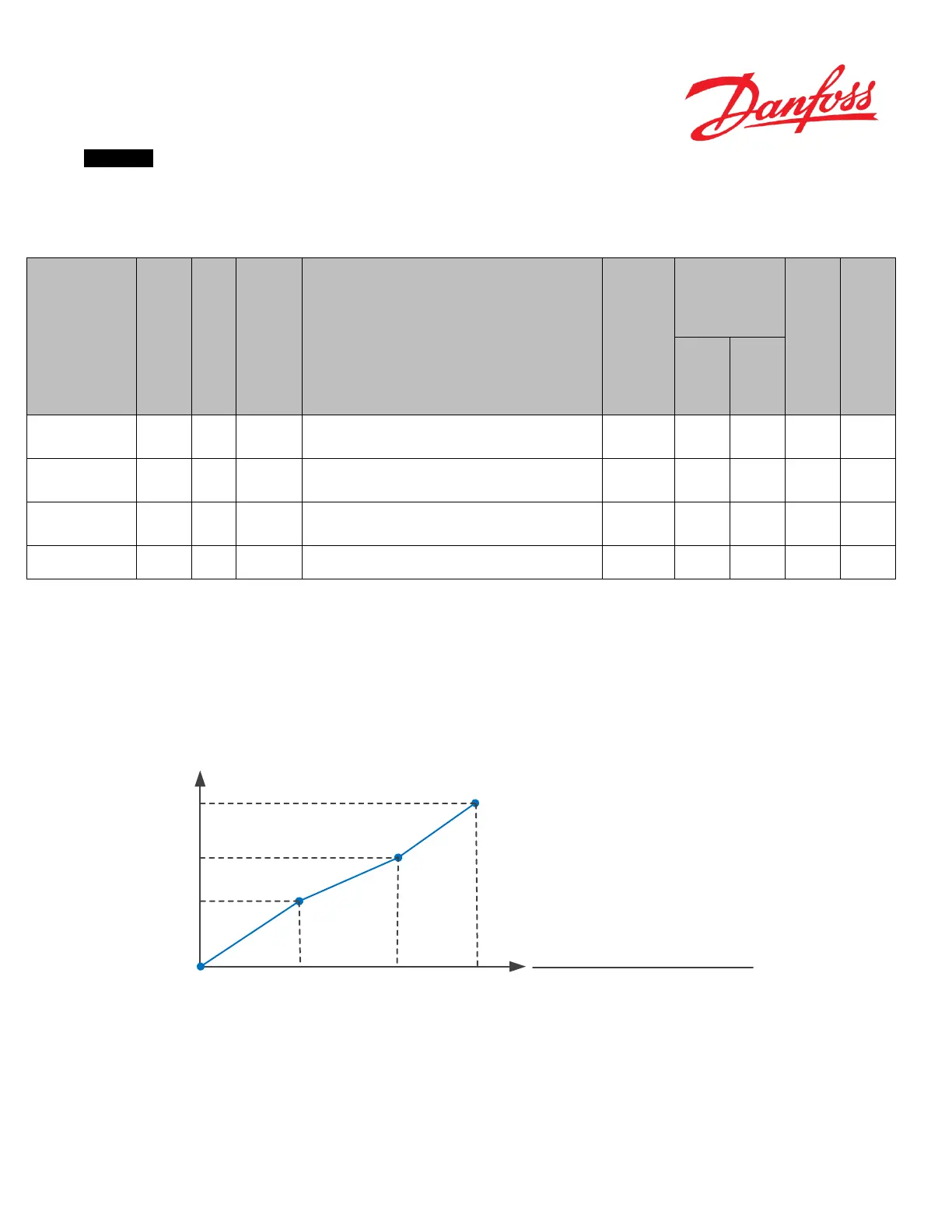
The sensor characteristics needs to be mapped, according to Figure . The cylinder stroke volume @ 33% (P3815), 67%
(P3817) and 100% (P3819) of the voltage base (P3821) should be mapped, where voltage base is:
The absolute voltage [mVolts] from the WAS, going from neutral to left most position, when maximum possible steer
angles can be achieved on the vehicle + some tolerance.
0.33 0.67 1.00
P3819
P3817
P3815
Automatic adjusted
cylinder stroke volume
(steering left)
|Captured left most position – Captured neutral position|
P3821
Figure 19