Required tools
You can perform the service procedures in this manual using common mechanic’s hand-tools. Calibrate
gauges frequently to ensure accuracy. Use snubbers to protect pressure gauges.
Port locations and pressure gauge installation
A pump with a manual displacement control (MDC) and no filtration adapter is shown. With non-
feedback controls, the positions of the case drains may vary. With a filtration adapter, the porting in the
filtration options area varies.
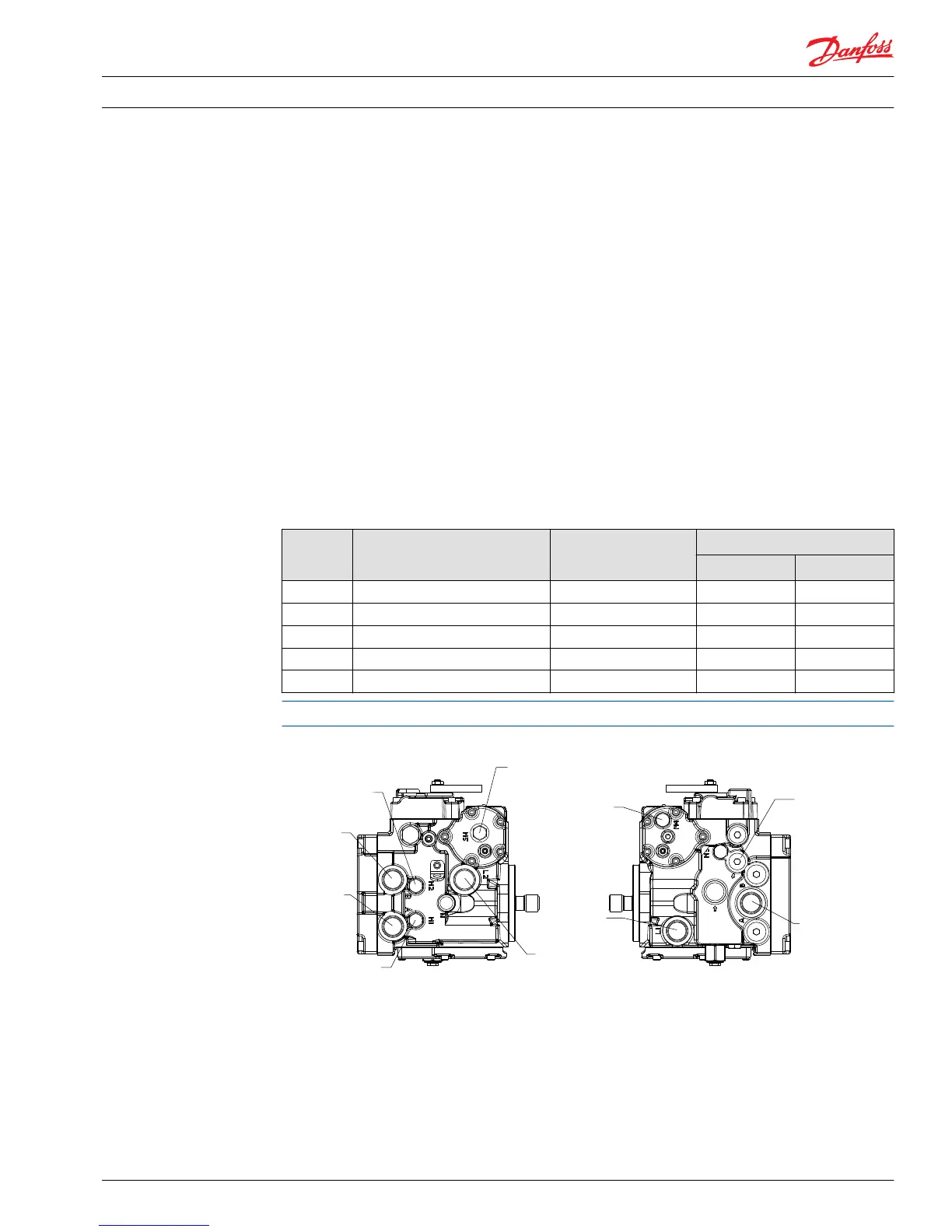
Ports and pressure gauges
Proper service and diagnosis may require pressure measurement at various points in the hydraulic circuit.
The Series 42 pump has several locations at which to take these measurements. The following illustration
shows the locations of the various gauge ports. The table shows the recommended gauge size and the
fitting size for each port. Refer to this information when installing pressure gauges.
Gauge ports
Gauge
port
Pressure measured Recommended gauge
size
O-ring boss
28/32 cc 41 / 51 cc
M1 & M2 System pressure for ports A and B 600 bar [8700 psi] 9/16/-18 9/16/-18
M3 Charge pressure 60 bar [870 psi] 3/4-16 * 3/4-16 *
M4 & M5 Servo pressure 60 bar [870 psi] 9/16-18 9/16-18
L1 & L2 Case pressure 35 bar [510 psi] 1-1/16-12 1-5/16-12
S Charge pump inlet pressure 1 bar [30 in Hg vacuum] 1-1/16-12 1-5/16-12
* Some older models may use a 9/16-18 O-ring fitting.
28/32 cm
3
base unit with MDC and no filtration adapter