Replacement
1. Clean the sealing surfaces of the control and the pump housing. Place a new gasket (E001) in position
on the housing.
The control orifices are part of the control gasket. Refer to the appropriate Service Parts List to
determine the correct gasket.
2. Hold the summing link pin (D011) in position while installing the control. The link pin MUST engage
the hole in the control slider block (see diagram on previous page).
Warning
Failure to properly engage the summing link pin with control slider block will result in incorrect
control operation, which may lead to loss of control of the vehicle / machine.
Lay the servo piston side of the control down first, then watch the link pin engage from the charge
pump side of the pump.
3. Install the control bolts (D081/D082), torque to 17 N•m [13 lbf•ft].
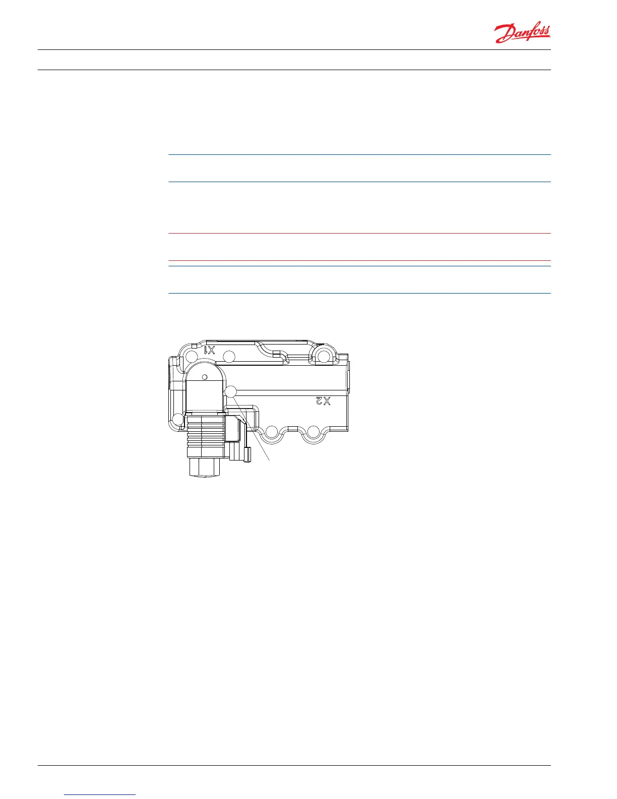
Torque patterns (MDC, EDC and HC-EDC)
4. Replace the spring (D91). Install new O-rings on control spool plugs (D032 and D035). Install plugs
and torque to 70 N•m [52 lbf•ft].
5. Adjust the neutral position of the control as shown in Control neutral adjustment for MDC and EDC/HC-
EDC on page 33.
MDC/EDC Spool, linkage, and neutral adjustment screw
You may remove the control spool, control linkage, and control neutral adjustment screw for cleaning
and to change the O-rings or the seal lock nut.
Removal
1. Clean the external surfaces of the pump.
2. Remove the MDC, EDC or HC-EDC module and the control gasket from the pump housing. Discard
gasket. See pages 35 through 38 for control removal procedure.
3. Remove the summing link (D011). Note the manner in which the parts are assembled and the way the
summing link engages the control spool (D090).
Remove the summing link by sliding it off the feedback link.
Service Manual
Series 42 Axial Piston Closed Circuit Pumps
Minor Repair
44 520L0638 • Rev 0300 • July 2015
 Loading...


