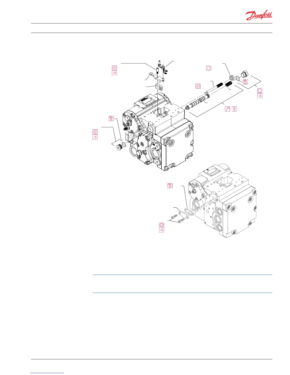
4. Using a 4mm internal hex wrench, remove the summing link pivot pin (D010). Slide the feedback link
(D012) towards the servo piston to disengage the neutral adjustment link (D013). You can now
remove all linkages.
5. Remove the two bore plugs (D032 and D035). Note the orientation of the control spool (D90) and
which side of the pump the spring (D91) is located (spring is on the opposite side from the filter
adapter). Remove spring and spool.
Prior to the 1998 block point change, the full-featured 28 cm
3
housing for the Series 42 pump used a
control spool cover (F035), gasket (F034), and two screws (F036) instead of a bore plug on the control
spool’s non-spring side. Discard the control gasket (F034) and thoroughly clean the mating surface.
6. Remove the control neutral adjustment seal nut (D015) and screw (D014).
Installation
1. Install the control neutral adjustment screw (D014) and seal lock nut (D015). Do not tighten the nut.
2. Lubricate and install the control spool (D90) and spring (D91), noting proper orientation. Install the
two side bore plugs and torque to 70 N•m [52 lbf•ft].
3. Replace the summing link, feedback link, and neutral adjustment link.
First combine the center pin of the feedback link (D012) with the mating bore of the neutral
adjustment link (D013). Insert the end of the feedback link into the servo piston slot. Mate the neutral
adjustment link with the control neutral adjustment screw (D014). Insert the linkage pivot screw
Service Manual
Series 42 Axial Piston Closed Circuit Pumps
Minor Repair
520L0638 • Rev 0300 • July 2015 45
 Loading...


