Assembly
1. Replace the NFPH control orifice plugs (E0 51, E052) if they were removed.
2. Install new gaskets (L002/M002).
3. On the right side, thread the servo piston cover (L001) onto the neutral adjustment screw. Then, while
holding the cover, turn the neutral adjustment screw (T015) counter-clockwise to run the cover down
the screw threads.
Warning
Unintended vehicle movement hazard: When you remove the right side servo piston cover, you must
set neutral and control neutral. Refer to Control neutral adjustment for MDC and EDC/HC-EDC on page
33.
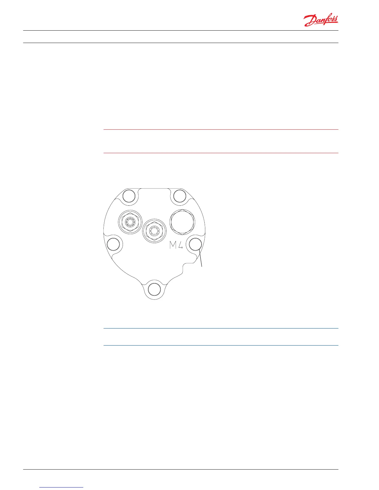
4. Using a T30 Torx driver or 5 mm internal hex, install the servo piston cover screws (L005/M005).
Torque to 17 N•m [13 lbf•ft] in the pattern shown.
Bolt torque patterns
5. Install a new seal lock nut (T060) onto the neutral adjustment screw (T015). Do not torque at this time.
6. Perform pump neutral adjustment and control neutral adjustment procedures. Refer to Control
neutral adjustment for MDC and EDC/HC-EDC on page 33.
Removal of the servo covers may change the position of the displacement limiters; readjust if
necessary.
Loop flushing and loop flushing relief valve
The loop flushing function consists of the loop flushing shuttle valve and the loop flushing relief valve.
You may remove the assemblies for cleaning and installation of new O-rings. You may exchange the relief
valve poppet for one with a different flow rating. Take notice, though, pre 1998 models contained relief
shims, do not change these shims unless Danfoss specifically instructs you to do so. You may also defeat
the loop flushing function by installing a defeat spool.
Series 42 pumps built prior to 1998 use unique loop flushing spools. Post 1998 release pumps use a
common loop flushing spool. They are not interchangeable.
Service Manual
Series 42 Axial Piston Closed Circuit Pumps
Minor Repair
62 520L0638 • Rev 0300 • July 2015
 Loading...


