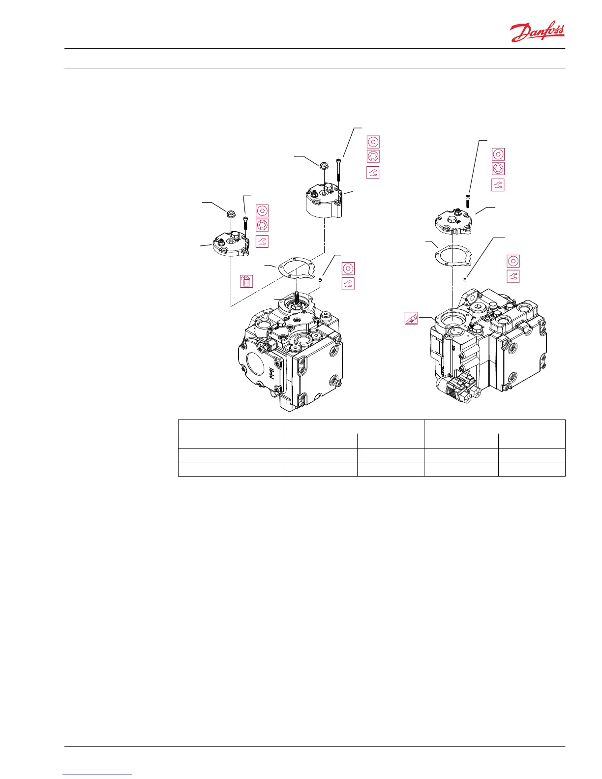
Frame size cm
3
28/32 41/51
Control MDC/EDC/HC-EDC NFPE/NFPH MDC/EDC/HC-EDC NFPE/NFPH
Lock nut 13 mm 17 mm 17 mm 17 mm
Servo adjust screw 5 mm 7 mm 7 mm 7 mm
Disassembly
1. Remove locknut (T060) from the right side servo cover.
2. Using a T-30 Torx driver or 5 mm internal hex, remove the servo cover bolts (M005). Post 1998 release
pumps have cover bolts that are 10 mm [0.39 in] longer than pre-1998 pumps. The longer bolts are
only compatible with post-1998 pump housing.
3. Remove the servo piston covers (L001/M001).
To remove the right side servo cover turn the neutral adjustment screw (T015) clockwise (inward) far
enough for the servo cover to clear the nearby case drain port. Then pull the cover away from the
housing and turn the cover counterclockwise to remove it from the adjustment screw.
4. Remove the gaskets (L002/M002). Clean gasket surfaces.
5. NFPH control orifice plugs (E051 and E052) are located beneath the servo covers. If necessary, remove
and clean the orifices.
Service Manual
Series 42 Axial Piston Closed Circuit Pumps
Minor Repair
520L0638 • Rev 0300 • July 2015 61
 Loading...


