4. Then turn the sensor clockwise (CW) until the wrench flats on sensor body are positioned at a 22°
angle to the pump shaft center line.
Most adjustable wrenches have a 22° handle offset.
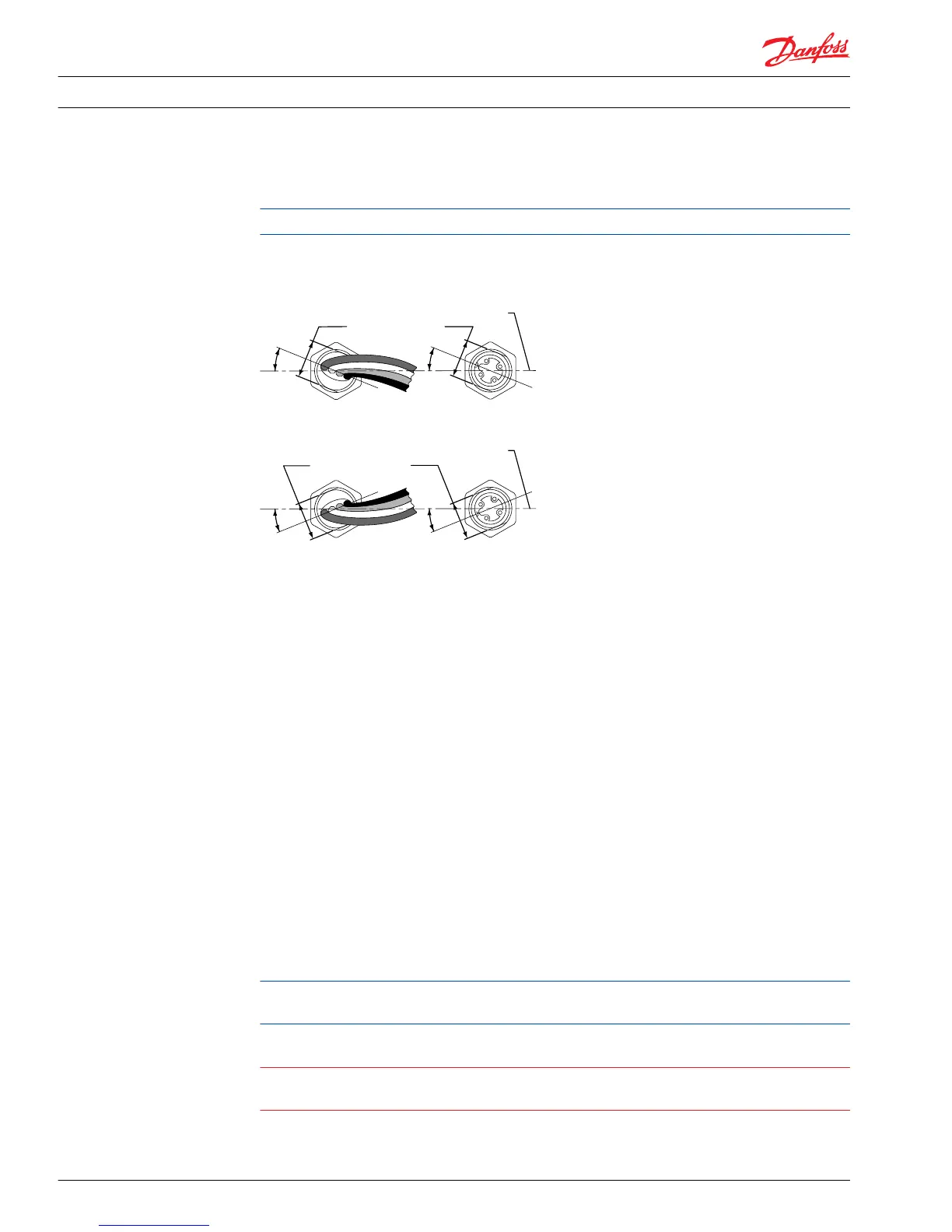
5. The final sensor position should be between 1/2 (180°) and 1/4 turn (90°) counterclockwise (CCW)
from the point where the sensor contacts the speed ring.
Positioning speed sensor relative to pump shaft
6. Hold sensor in position with a 1/2 inch hex wrench while tightening the lock nut to 13 N•m [10 lbf•ft].
MDC Module
Removal
The manual displacement control (MDC) actuates the control spool through a connection to the
summing link pin. The following procedure describes how to remove and install the control. Control
spool and linkage removal is explained on pages 39 and 40.
1. Clean external surfaces of the pump. If necessary, remove the MDC handle (D017) and disconnect NSS
wiring (D040).
2. Being careful not to lose the backlash spring (D91), remove the control spool plugs (D032 and D035).
3. Remove the seven (7) control bolts (D002) that secure the control to the pump housing. Remove the
control (D070) and gasket (E001) from the pump. Discard the gasket.
4. Ensure that the housing and control surfaces are clean and free of gasket material. If necessary, clean
the surfaces with solvent.
Installation
1. Place a new gasket (E001) on the control module
The control gasket acts as regulating orifices. Check the Parts Manual (28 cm
3
, 520L0590; or 41 cm
3
,
520L0589) and your order code to confirm you have the correct control gasket.
Warning
Unintended vehicle/machine movement hazard. MDC must be aligned to the housing within 0.005
inch. Inaccurate alignment may cause neutral to be off center or make it impossible to set.
Service Manual
Series 42 Axial Piston Closed Circuit Pumps
Minor Repair
40 520L0638 • Rev 0300 • July 2015