Overview
This section offers instruction on how to perform adjustments to the Series 42 pump. Read through the
entire procedure before beginning any service activity.
Displacement limiter adjustment
Mount the pump on a test stand capable of measuring system flow from the A and B ports.
1. Loosen the displacement limiter seal lock nut (L025), but do not remove it.
2. Start the prime mover and place the pump into full stroke in one direction. Note the system output
flow from either the A or B system port.
3. Adjust the displacement limiter adjustment screw (L020) until the desired output flow is reached.
Turning the displacement limiter adjustment screw clockwise decreases the maximum output flow
setting. Turning the displacement limiter adjustment screw counter clockwise increases the
maximum output flow setting.
Warning
The seal nut lock nut must be retorqued after every adjustment and the limiter screw must have full
thread engagement in the servo piston cover to prevent unexpected changes in operating conditions
and to prevent external leakage during unit operation.
The pump achieves overall maximum flow when the displacement limiter does not contact the servo
piston while the unit is in full stroke.
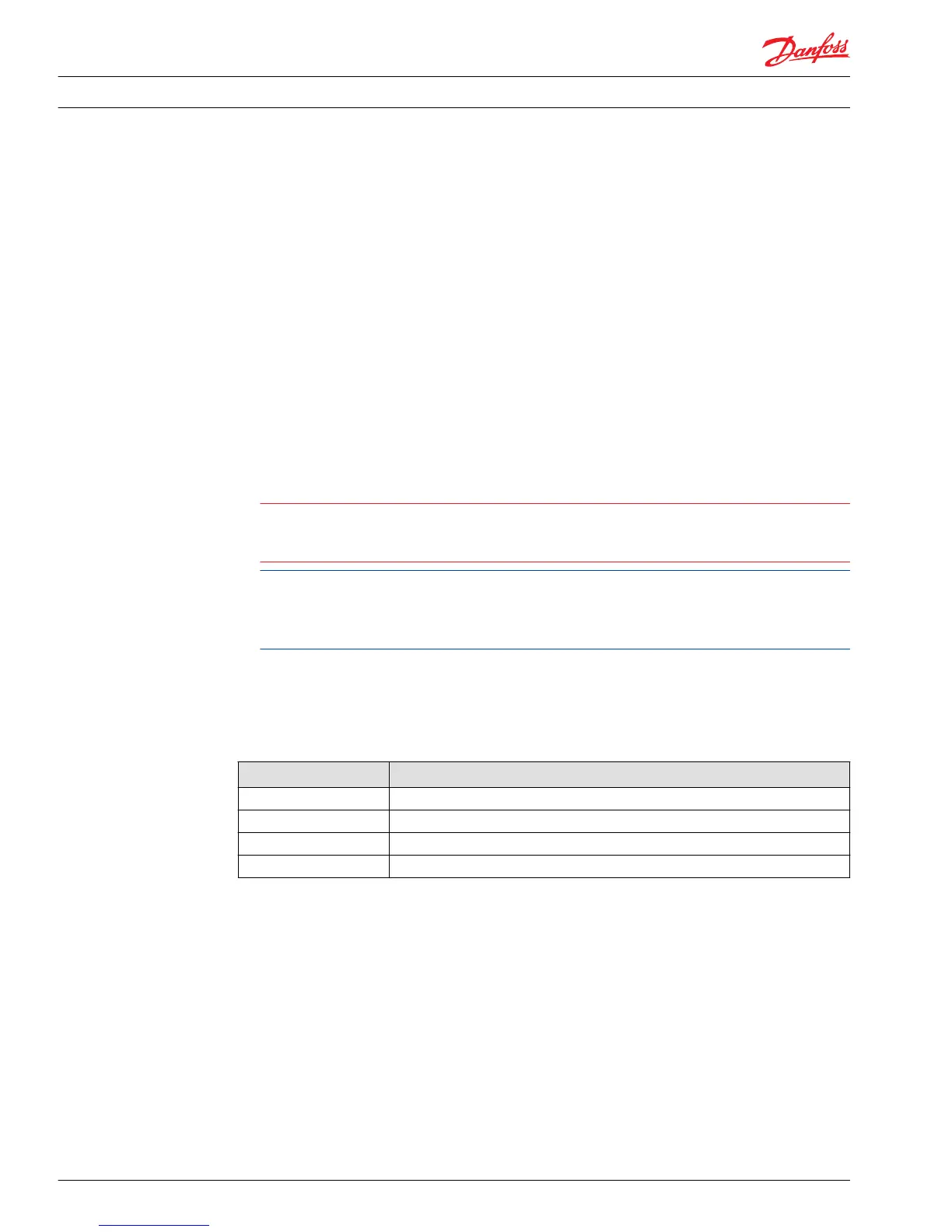
One full turn of the displacement limiter adjustment screw results in approximate flow output
changes per the table.
4. Once you achieve the proper output flow, torque the displacement limiter seal lock nut (L025) to 23
N•m [17 lbf•ft] while holding the position of the adjustment screw (L020).
5. If required, repeat this procedure using the opposite displacement limiter to set the output flow in
the other direction.
Displacement limiter adjustment
Size Displacement change per turn
28 cm
3
3.6 cm
3
/rev [0.22 in
3
/rev]
32 cm
3
4.1 cm
3
/rev [0.25 in
3
/rev]
41 cm
3
5.0 cm
3
/rev [0.31 in
3
/rev]
51 cm
3
6.2 cm
3
/rev [0.38 in
3
/rev]
Service Manual Series 42 Axial Piston Closed Circuit Pumps
Adjustments
30 520L0638 • Rev 0300 • July 2015