Pump neutral adjustment
Zero output flow from the pump defines the neutral condition. To attain zero output flow, the pump
must achieve both mechanical neutral and control neutral conditions. Mechanical neutral is the condition
when the swashplate is at zero angle without any signal input from the control. Set mechanical neutral
prior to setting control neutral.
Warning
To prevent injury, disable the machine: raise wheels off the ground or disconnect the mechanism.
1. Disable the control input to the pump by equalizing the pressures on both ends of the pump servo
piston. To accomplish this, connect an SAE‑06 hose between servo gauge ports, M4 and M5.
2. Install pressure gauges in gauge ports M1 and M2 to measure system pressure.
3. Start the prime mover and run at normal operating speed.
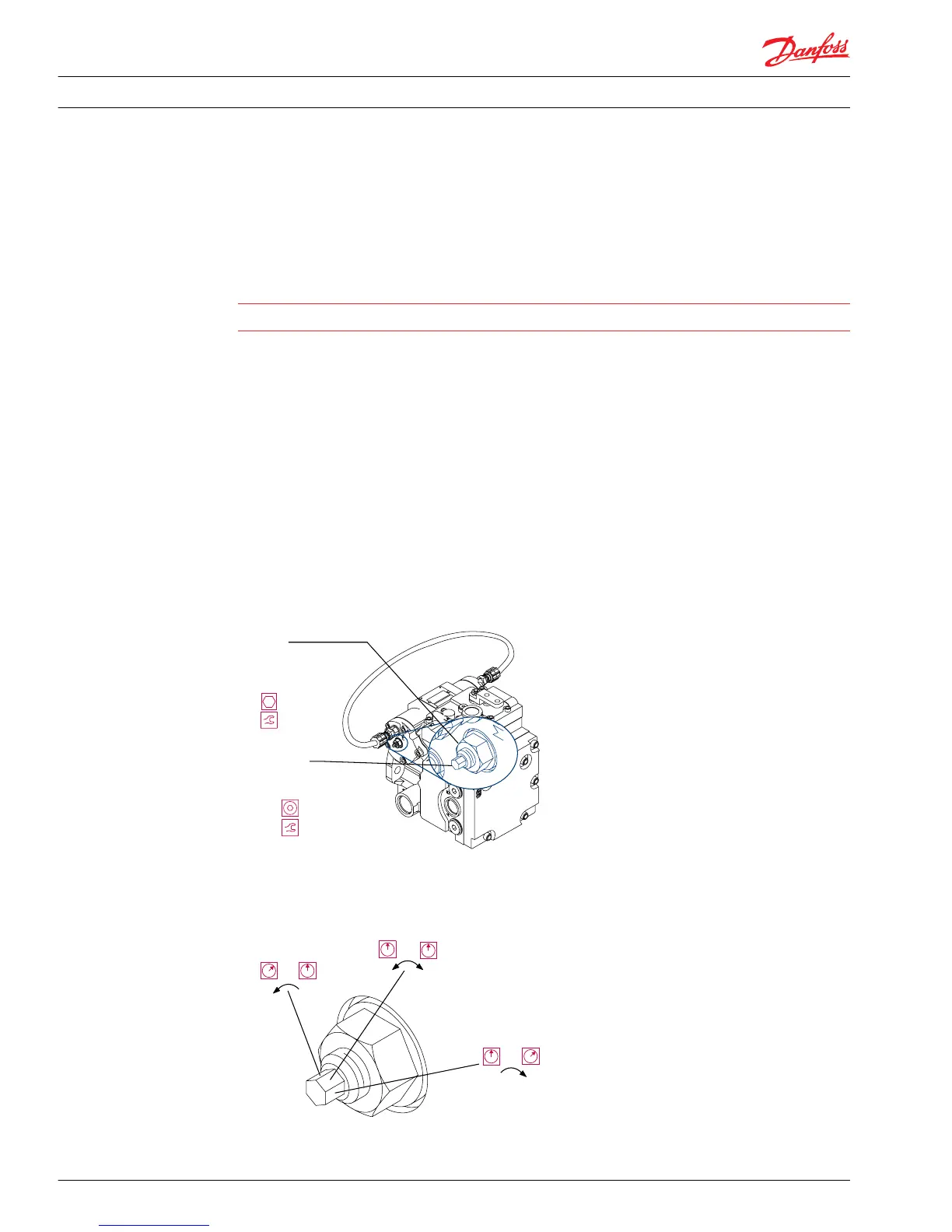
4. Loosen the pump neutral adjustment seal lock nut (T060) in the center of the servo cover on the right
side of the pump.
5. Turn the adjustment screw (T015) clockwise until one of the gauges registers an increase in system
pressure. Mark the position of the adjustment screw. Turn the screw counterclockwise until the other
gauge registers an increase in system pressure. Mark the position of the adjustment screw. Turn the
adjustment screw clockwise to a position halfway between the marks. The system pressure gauges
should indicate equal pressures.
6. While holding the adjustment screw in position, torque the seal lock nut (T060). Torque 28/32 cm
3
models with an MDC, EDC or an HC-EDC to 20-26 N•m [15-19 lbf•ft]. Torque all 41/51 cm
3
models and
28/32 cm
3
models with NFP controls to 40 N•m [30 lbf•ft].
Pump neutral adjustment screw
7. Stop the prime mover and remove the hose between gauge ports M4 and M5. Remove the pressure
gauges in gauge ports M1 and M2. Reinstall the plugs in the gauge ports.
Neutral adjustment gauge port readings
8. Proceed to the control neutral adjustment section on the next page.
Service Manual
Series 42 Axial Piston Closed Circuit Pumps
Adjustments
32 520L0638 • Rev 0300 • July 2015
 Loading...


