Externally adjustable style
The 1998 block point change discontinued the use of the shim adjustable charge relief valve and made
the externally adjustable charge relief valve standard. The charge pressure changes by approximately 1.4
bar (20 psi) per quarter turn of the adjustable charge relief valve plug (this applies to both external and
internal hex style plugs).
1. Mark the adjustable charge relief valve plug (T039), lock nut (T041), and the pump housing prior to
removing the charge relief valve in order to approximately duplicate the charge pressure relief valve’s
original setting upon reassembly.
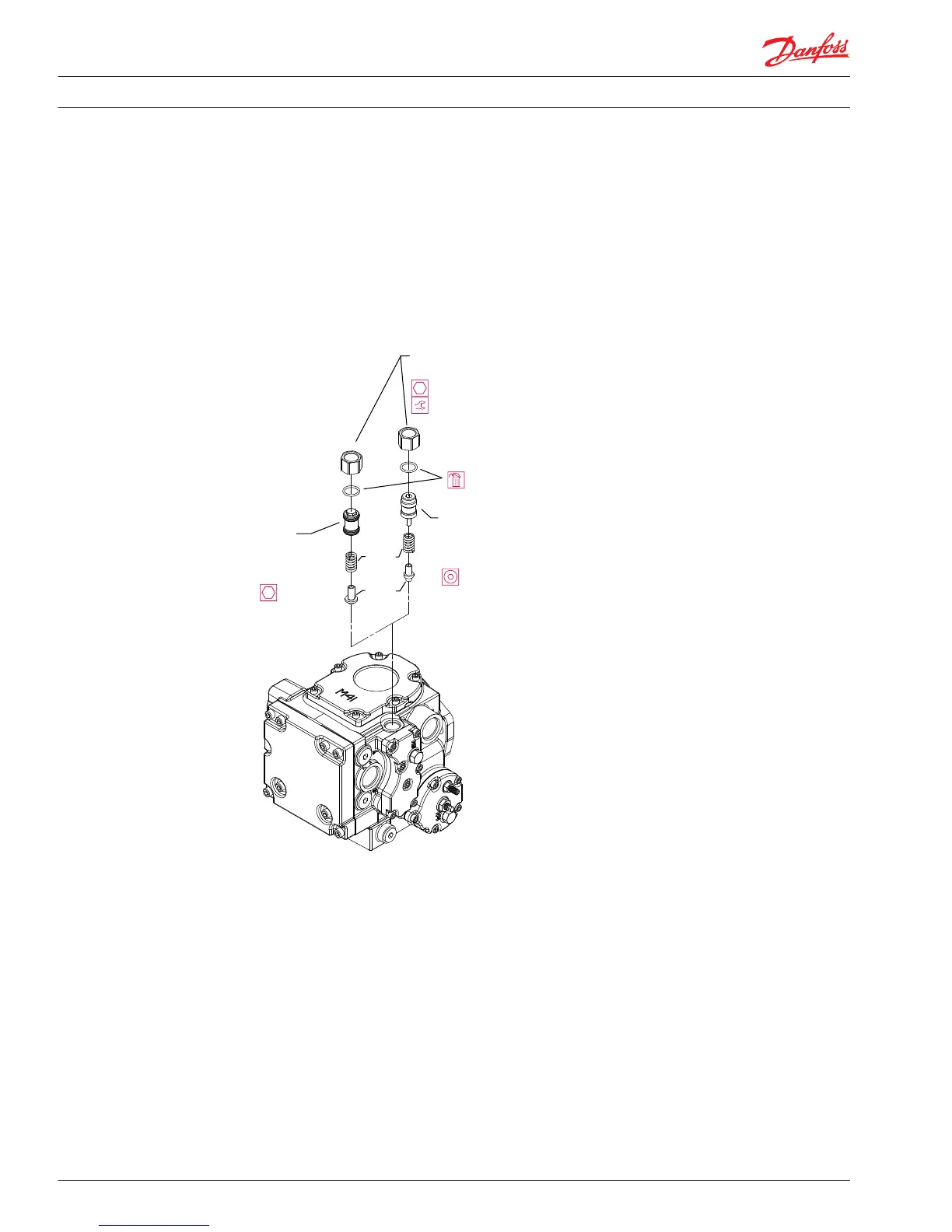
Externally adjustable charge relief valve components
2. Loosen the lock nut (T041) and unscrew the adjustable charge relief valve plug (T039).
3. Remove and discard the O-ring (T039A) from the adjustable charge relief valve plug (T039).
4. Remove the spring (T042) and poppet (T043) from the housing.
5. Inspect the poppet (T043) and seat within the housing for damage or foreign material. Replace as
necessary.
6. Install the poppet (T043) and spring (T042) into the housing.
7. Install a new O-ring (T039A) onto the adjustable charge relief valve plug (T039).
8. Install the adjustable charge relief valve plug (T039) and the lock nut (T041) into the housing, aligning
the marks made prior to disassembly.
9. On 28/32 cm
3
models, torque the lock nut (T041) to 24 N•m [18 lbf•ft], and on 41/51 cm3 models,
torque the lock nut (T041) to 40 N•m [30 lbf•ft]. (This may cause misalignment of the original position
marks made earlier).
10. Confirm the charge relief valve setting by measuring charge pressure at the charge pressure gauge
port, (M3). The charge pressure reading should level off when the relief setting is reached.
Service Manual
Series 42 Axial Piston Closed Circuit Pumps
Minor Repair
38 520L0638 • Rev 0300 • July 2015