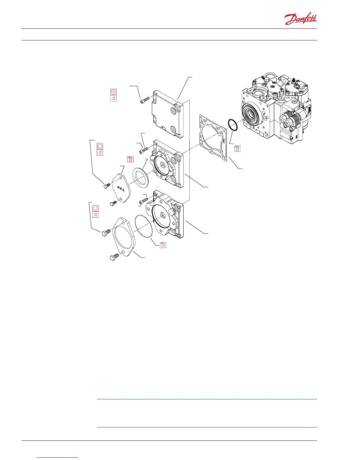
Removal of charge pump cover/auxiliary pad
1. Orient the pump so that the charge pump cover or pad (U040) is facing up.
2. If present, remove the auxiliary pump or cover (U085) by removing the two screws (U090). Discard the
O-ring (U080).
3. Remove screws (U035) retaining the charge pump cover/pad. Remove the charge pump cover/pad
(U040) and gasket (U030). You may reuse the gasket. Clean all mating surfaces.
4. Remove and discard charge pump seal (G023). Leave alignment pins in the housing.
Installation
1. Inspect the charge pump cover/pad gasket (U030) and mating surfaces. If undamaged, you may reuse
the gasket. Replace the gasket if you suspect leakage. Install the gasket.
2. Install a new charge pump cover/pad seal (G023).
3. Install the charge pump cover/pad (U040) Using a 6 mm internal hex torque the six or seven bolts
(U035) to 45 N•m [33 lbf•ft] using the pattern at the right.
4. Replace the O-ring (U080) and cover plate (U085) or auxiliary pump. Install and torque the two
mounting screws (U090). For SAE A pads, torque the mounting screws to 42 N•m [31 lbf•ft]. For SAE B
pads, torque the mounting screws to 100 N•m [74 lbf•ft].
The threaded screw holes in the auxiliary pump mounting pad in early production pumps with the
SAE A pad option go clear through the charge pump cover. Use M8x1.25 internal hex set-screws to
plug any holes not used to attach the cover plate or auxiliary pump. Install hand tight to prevent the
entrance of foreign material into the pump.
Service Manual
Series 42 Axial Piston Closed Circuit Pumps
Minor Repair
56 520L0638 • Rev 0300 • July 2015
 Loading...


