Service Monitor User Manual
Danfoss Turbocor Compressors Inc. 55
ECD-00007M Rev. 1
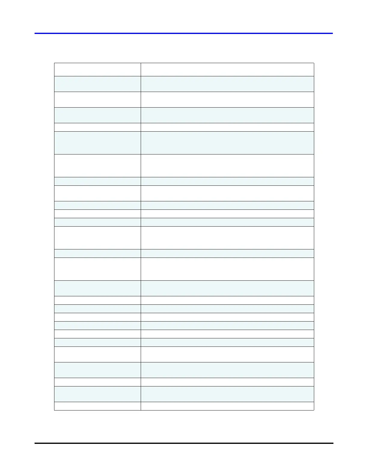
Discharge Pressure The actual discharge gauge pressure at the compressor flange
as measured by the discharge pressure transducer.
Suction Temperature The actual suction temperature at the compressor flange as
measured by the suction temperature/pressure transducer.
Discharge Temperature The actual discharge temperature at the compressor flange as
measured by the discharge temperature/pressure transducer.
Cavity Temperature Temperature of the superheated gas moving past the shaft.
Entering Air/Water Temp Temperature as measured from the 10K thermistor connected
to the terminals marked “ENTRY” on the Chiller Interface
module.
Leaving Air/Water Temp Temperature as measured from the 10K thermistor connected
to the terminals marked “LEAVE” on the Chiller Interface
module.
24VDC Supply Regulated 24V DC voltage as measured from the Backplane.
InterLock Status Interlock status:
either opened (denoted by 1.0) or closed (denoted by 0.0).
Surge Speed Minimum compressor speed [RPM].
Choke Speed Maximum compressor speed [RPM].
Stepper #1 PV Controlled variable maintained by the stepper motor #1 output.
Stepper #1 Position Ratio of the actual number of steps sent to the stepper motor
over the maximum number of steps the motor is allowed to
drive. Range: 0%-100%.
Stepper #2 PV Controlled variable maintained by the stepper motor #2 output.
Stepper #2 Position Ratio of the actual number of steps sent to the stepper motor
over the maximum number of steps the motor is allowed to
drive. Range: 0%-100%.
Cooling Solenoid Status Cooling solenoid status:
either open (denoted by 1.0) or closed (denoted by 0.0).
Axial Force Current required to counteract axial unbalance force [Amps].
FX Force Current required to counteract front x unbalance force [Amps].
FY Force Current required to counteract front y unbalance force [Amps].
BX Force Current required to counteract rear x unbalance force [Amps].
BY Force Current required to counteract rear y unbalance force [Amps].
Actual Speed Actual shaft speed in RPM.
Desired Speed Commanding shaft speed in RPM (always higher than the
actual shaft speed).
Motor Amps (Inverter Side) Current output from the IGBT Inverter to the motor (torque-
generating current component).
3 Phase Power (kW) 3-phase AC input power (mains input)
Inverter Temperature Inverter temperature as measured by thermistor mounted
under the IGBT Inverter.
Front Orbit Average Percentile indicating the average front orbit displacement.
Table 21 Trending Parameters (Continued)
Parameter Description

 Loading...


