1 or 5 A CT set-up
To allow for possible reuse of already present CT
transformers, the active filter allows use of either 1 A or 5
A CTs. The filter is as standard set-up for 5 A CT feedback.
If the CTs are 1 A, redirect the CT terminal plug from slot
MK101, position 1, to MK108, position 2, on the AFC card.
See Illustration 4.6.
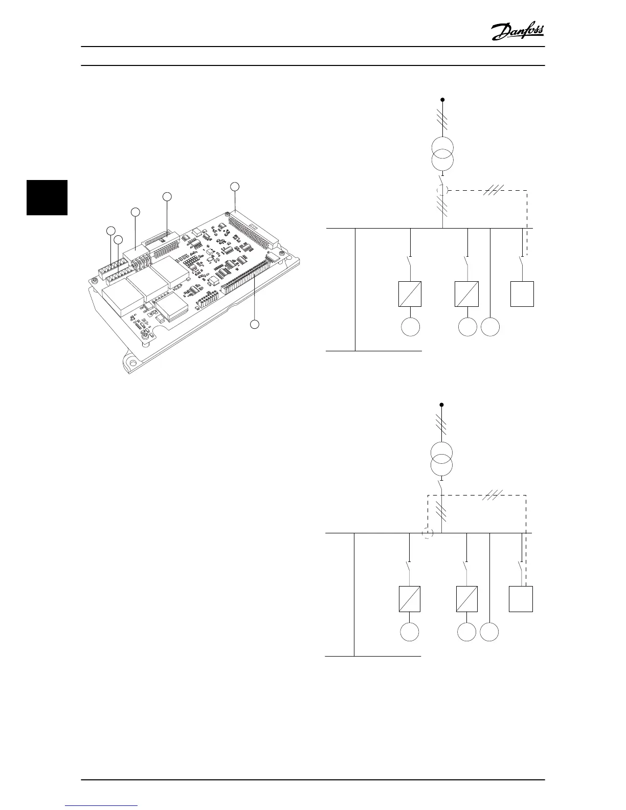
Illustration 4.6 AFC Card
Individual or group compensation
The compensation of the filter depends on the signal that
is returned from the current transformers. The point of
installation for these sensors is to determine the loads that
are corrected.
Illustration 4.7 shows current transformers installed in front
of the entire installation with the filter compensating all
loads on the transformer. Illustration 4.8 shows current
transformers installed in front of distribution bus 2 and 1
frequency converter, so the filter only compensates for
those.
M M
M
PCC1
PCC2
130BB511.11
AAF
Illustration 4.7 CT on PCC Side
M
M
M
PCC1
PCC2
130BB512.10
AAF
Illustration 4.8 CT on Load Side
If the CTs are installed on the secondary side of the
transformer and so in front of the entire load, the filter
compensates all loads simultaneously. See Illustration 4.7.
Electrical Installation
Operating Instructions
20 Danfoss A/S © 09/2014 All rights reserved. MG90V302
44