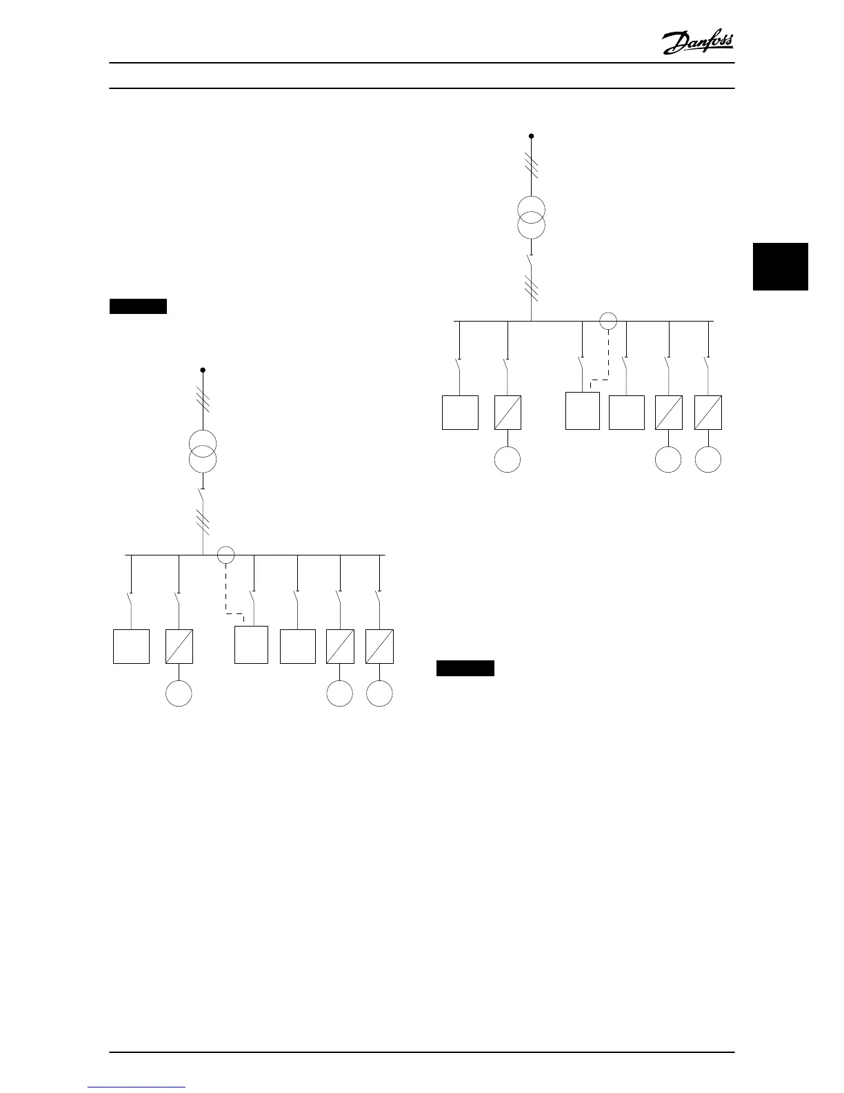
If, as in Illustration 4.8, the CTs are installed in front of only
some of the loads, the filter does not compensate
unwanted current deformation of the frequency converter
and motor on the right hand side. If CTs are installed in
front of a single load, the filter only compensates the 1
load and so form individual load compensation.
CTs can be installed on the source side (PCC–point of
common coupling), or on the load side via
parameter 300-26 CT Placement
NOTICE
The default setting is PCC side installation
Illustration 4.9 Current Transformers Installed on Source (PCC)
Side for Group Compensation
Illustration 4.10 Current Transformers Installed on Load Side
for Group Compensation
If the current transformers are installed on the source
(PCC) side, the filter expects a sinusoidal (corrected) signal
feedback from the 3 sensors. If the sensors are installed on
the load side, the received signal is subtracted from the
ideal sine wave to calculate the necessary corrected
current.
NOTICE
Erratic filter operation can be a result of incorrect current
transformers connection point programming
parameter 300-26 CT Placement.
Electrical Installation Operating Instructions
MG90V302 Danfoss A/S © 09/2014 All rights reserved. 21
4 4