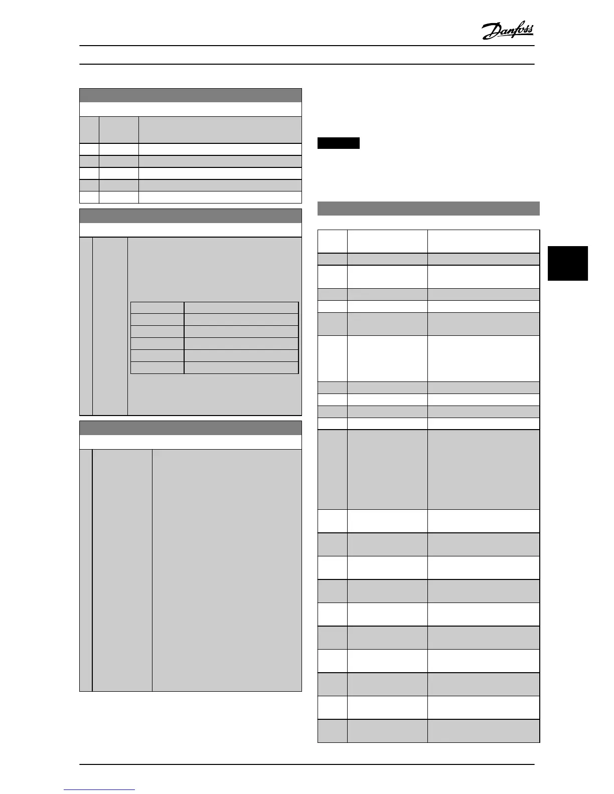
0-12 This Set-up Linked to
Option: Function:
Set-up 1. A switch between Set-up 1 and Set-up
2 during operation is now possible.
[0] * Not linked
[1] Set-up 1
[2] Set-up 2
[3] Set-up 3
[4] Set-up 4
0-13 Readout: Linked Set-ups
Range: Function:
0* [0 -
255 ]
View a list of all the set-ups linked by means of
0-12 This Set-up Linked to. The parameter has one
index for each parameter set-up. The parameter
value displayed for each index represents which
set-ups are linked to that parameter set-up.
Index LCP value
0 {0}
1 {1,2}
2 {1,2}
3 {3}
4 {4}
Table 6.7 Example: Set-up 1 and Set-up 2 are
linked
0-14 Readout: Edit Set-ups / Channel
Range: Function:
0* [-2147483648 -
2147483647]
View the setting of parameter 0-11 Edit Set-
up for each of the 4 different
communication channels. When the
number is displayed as a hex number, as it
is in the LCP, each number represents 1
channel.
Numbers 1-4 represent a set-up number; F
means factory setting; and A means active
set-up. The channels are, from right to left:
LCP, FC bus, USB, HPFB1-5.
Example: The number AAAAAA21h means
the following:
•
The frequency converter selected
Set-up 2 via a fieldbus channel.
This selection is reflected in
parameter 0-11 Edit Set-up.
•
A user selected Set-up 1 via the
LCP.
•
All other channels are using the
active set-up.
6.4.3
0-2* LCP Display
Define the variables displayed in the LCP.
NOTICE
Refer to 0-37 Display Text 1, 0-38 Display Text 2 and
0-39 Display Text 3 for information on how to write
display texts.
0-20 Display Line 1.1 Small
Option: Function:
Select a variable for display in
line 1, left position.
[0] None No display value selected.
[1501] Running Hours Running hours meter of the
unit.
[1600] Control Word Present control word
[1603] Status Word Present status word.
[1630] DC Link Voltage Intermediate circuit voltage in
the unit.
[1634] Heatsink Temp. Present heat sink temperature
of the unit. The cut-out limit is
95 ±5 °C; cutting back in occurs
at 70 ±5 °C.
[1635] Inverter Thermal Percentage load of the inverters.
[1636] Inv. Nom. Current Nominal current of the unit.
[1637] Inv. Max. Current Maximum current of the unit.
[1639] Control Card Temp. Temperature of the control card.
[1660] Digital Input Signal states form the 6 digital
terminals (18, 19, 27, 29, 32 and
33). There are 16 bits in total,
but only 6 of them are used.
Input 18 corresponds to the
leftmost of the used bits. Signal
low=0; Signal high=1.
[1666] Digital Output [bin] Binary value of all digital
outputs.
[1671] Relay Output [bin] Binary value of the relay
outputs.
[1680] Fieldbus CTW 1 Control word (CTW) received
from the bus master.
[1684] Comm. Option STW Extended Fieldbus communi-
cation option status word.
[1685] FC Port CTW 1 Control word (CTW) received
from the bus master.
[1690] Alarm Word One or more alarms in a hex
code.
[1691] Alarm Word 2 One or more alarms in a hex
code.
[1692] Warning Word One or more warnings in a hex
code.
[1693] Warning Word 2 One or more warnings in a hex
code.
[1694] Ext. Status Word One or more status conditions
in a hex code.
Applications and Basic Prog... Operating Instructions
MG90V302 Danfoss A/S © 09/2014 All rights reserved. 43
6 6